This workshop is intended to guide you through some basic coding techniques, teach you the basics of designing electric circuits, and give you an introduction to programming an Arduino or Teensy board. If at any point you have a question, please ask one of the HURC members for guidance; we're here to help!
Before starting this workshop, you should have the following parts:
- A Teensy LC
- A USB micro cable for connecting the Teensy
- A breadboard
- Jumper cables
- 3 LEDs
- 2 pushbuttons
- Some resistors
- A Multimeter
The first step that needs to be completed before any coding can be done is to set up the correct environment. Since we will primarily be using Arduino or Teensy boards to program our robots, it is ideal for us to develop in the Arduino IDE. IDE is short for Integrated Development Environment, which contains not only the text editor we need to write our code in, but also a compiler to build our code, and communication protocols with the chip that we are programming. Arduino/Teensy boards are small boards that contain a microcontroller and easy to use interfaces for programming the processor and using it to control electronics. The Arduino IDE will allow us to program both Arduino and Teensy boards. Follow the steps below to get the Arduino IDE installed:
-
Click here to access the download page (we're using a slightly older version, 1.8.6, to maintain Teensy support).
-
Download your appropriate installer, depending on what operating system your machine has.
-
Run the installer, and leave all options in their default states. Note: On Windows, you will get a pop up asking to install the Arduino USB Driver. This is very important, so click allow.
-
Once the install finishes, close the installer, and you should have the Arduino IDE installed on your computer!
With the Arduino IDE installed, we can install an add-on that will also allow us to program Teensy boards from the Arduino IDE! Click here to access the download page for the Teensyduino add-on program. Follow the instructions on the page to get the Arduino IDE setup with the Teensyduino add-on program.
Now that you have your computer ready, it's time to brush up on the basics. We will first look at electronics and then at coding.
First lets dive in to the world of electrical circuits. If you already feel very confident in the material that is covered, feel free to skim or skip it.
The first thing you need to know before getting started are the components most used in electronic circuits and how they work (at a very high level). The following are the components that you will need to know in order to begin building simple circuits (and, subsequently, simple robots). Figure 0.1 shows how a component is represented in a circuit schematic, and directly below are pictorial representations.
- Power sources - A power source provides the voltage (Volts) and current (Amperes) necessary to drive a circuit. At its core, it is a source of electric potential, and without it a circuit would be useless. Power sources can take the form of batteries, power supplies, or microcontrollers. For simplicity, we will be using the Teensy LC as a power source. Connect the micro-USB end of the USB wire into the Teensy, and the USB end into your computer. Now, the "3V" pin on the Teensy can be used like a 3.3V power source!
- Resistors - Resistors (Ohms), to put it simply, resist. They impede the flow of electrons through a circuit and subsequently create a voltage drop. A voltage drop is a change in the amount of voltage in the circuit, allowing one to control how a circuit behaves fairly accurately. One thing to know is that current follows the path of least resistance, thus if a current has a choice between a 500 Ohm resistor and a 10000 Ohm resistor, most of it will flow through the 500 ohm resistor.
- Potentiometers (aka pots) - Potentiometers are essential variable resistors. While a resistor can only have a fixed resistance, potentiometers can be tuned to any resistance within its range.
- LEDs - LED stands for Light Emitting Diode. In its simplest form, it turns current into light and heat, while at the same time acting like a resistor and producing a voltage drop. Because LEDs are diodes, it is important to know that they only work if connected in the proper direction (the longer leg is the positive end, the shorter leg is the negative end).
- Capacitors - Capacitors act like buckets for electricity; they store charge and can thus be used as temporary and small batteries (as well as producing some other useful phenomenon). Capacitors, like LEDs, are polarized and will only work if placed in circuit in the correct orientation.
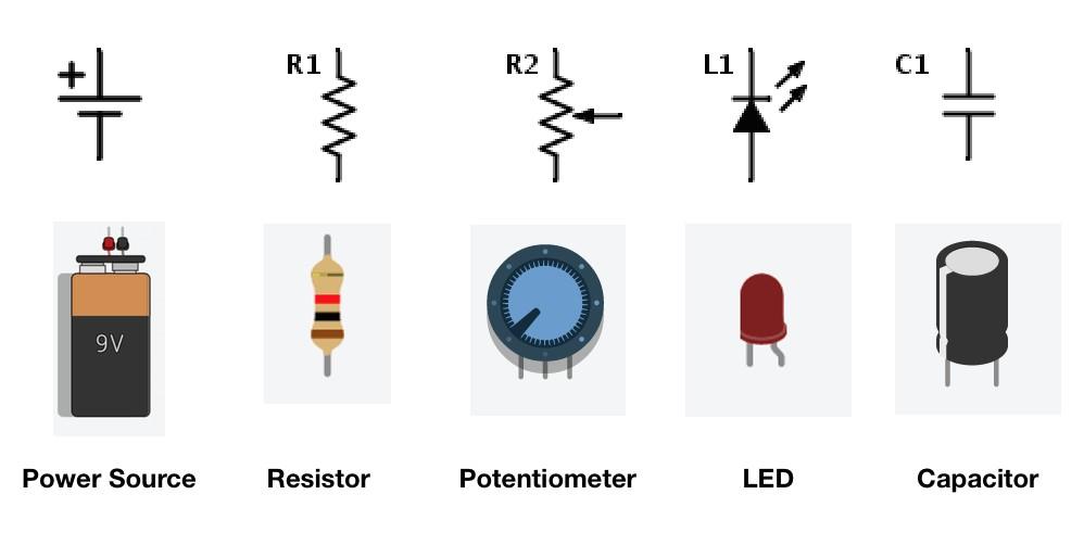
Figure 0.1: Basic electrical components
The next important step is learning the layout of the breadboard. A breadboard is a tool made for the quick prototyping of circuits. It is easy to build circuits and fix mistakes on a breadboard because components and wires are stuck into the sockets of a breadboard rather than being soldered together permanently. Figure 0.2 shows the layout of an example breadboard. From the image you can see that if a breadboard is held vertically, the rows in the middle are connected together and essentially act as a single point. Similarly, the columns to the left and right of the breadboard are connected together. The rows are where you will be connecting most of your components and the columns are usually used for power and ground.
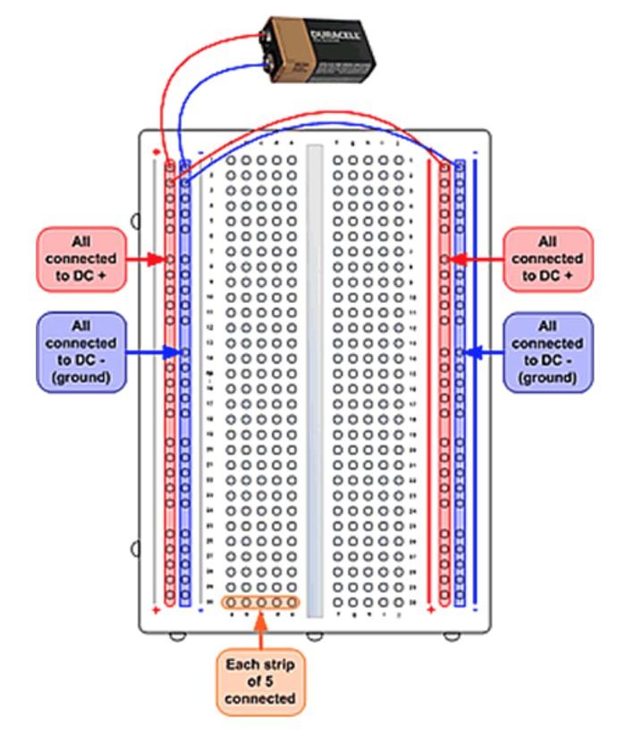
Figure 0.2: A standard breadboard
Ohm's Law is as follows: V = I * R, where V is voltage, I is current and R is resistance. In other words, the voltage drop across 2 points is proportional to the current flowing between those points and the resistance between the points. This formula (perhaps the most important in all of electronics) is extremely useful for most simple circuits and for all the circuits being built today. The linear relation between V and I or V and R means that if we know any of the two values of a circuit, we can calculate all parameters that define how it works. We also have the power equation: P = V * I = I^2*R = V^2 / R, where P is power. The power value in an LED will determine how bright it shines and in a resistor, how much heat it will dissipate.
Looking at the schematic in Figure 0.3 you can see that the LED and resistor are in series in the circuit diagram. On a breadboard components in series need to share at least one row, as it allows for one component to conduct to another.
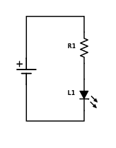
Figure 0.3: An LED and resistor in series
Looking at the schematic in Figure 0.4 you can see that the resistor and capacitor are in parallel in the circuit diagram. On a breadboard components in parallel need to share both rows as points of contact. When components share rows in this way, current must flow into both of them at the same time, thus making the connection a parallel one.
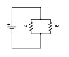
Figure 0.4: 2 resistors in parallel
1.1. Build the circuit in Figure 0.3 and watch the LED come to life. For our LEDs, any resistor value greater than 100 Ohms should work in these exercises, but the larger the resistance the less bright the LED will be! Too little resistance and the LED could burn out. If you burn out an LED it's no problem, just let a HURC member know and we'll get you a new one!
1.2. Kirchhoff's current law may be just as important as Ohms law in circuit analysis. It basically means that the amount of current entering a junction is equal to the current exiting the junction. That is Σ I = 0. In simpler terms, this law says that the amount of current entering a set of parallel components does not have to be equal; current splits. Voltage on the other hand is the same. Thus, the power that a certain component gets is affected by whether or not it is in series with something else. Build the circuit in Figure 0.5. Now what happened to the brightness of the LED?
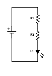
Figure 0.5: An LED with 2 resistors in series
1.3. Now rebuild your circuit, so that it looks like the one in figure 0.6. What happened to the brightness of the LED? Why?
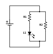
Figure 0.6: An LED and 2 resistors in parallel
A multimeter is used to measure the V, I, and R -values at certain points in a circuit. Instead of using multiple separate devices, you can simply turn the dial on a multimeter to turn it into a voltmeter, ammeter or some other measurement device. The way multimeters measure voltage, current, and resistance are fundamentally different. A voltmeter must be placed in parallel to what you want to measure in order to find the voltage. An ammeter on the other hand must be placed in series with the circuit; the best way to do so is to pretend that it is another resistor. In Figure 0.7 you can see how a voltmeter and ammeter are placed properly in order to measure voltage or current. In order to measure the resistance of an element, you have to connect the multimeter in parallel to the component, similarly to how you would measure voltage.
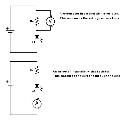
Figure 0.7: How to properly connect a voltmeter and ammeter
2.1. Build the circuit from Figure 0.3. First measure the voltage of the power source by placing the probes in the buses of the breadboard (if the probe doesn't fit in to the holes, use a piece of wire to make the connection). Next, measure the voltage across the LED by placing the voltmeter in parallel with it. Next measure the voltage across the resistor. What do you notice about the voltage drops?
2.2. Now measure the current in the circuit at various places (before the LED, between the LED and the resistor, and after the resistor). What do you notice about the current?
2.3. Now rebuild the circuit from Figure 0.6 and make similar measurements. What do you notice? Can you explain what you see?
Hopefully you have learned the difference between components in parallel and components in series. When in series, V will change at every interval, but current will stay the same. When in parallel, V will stay constant throughout, but current will change depending on what branch of the parallel tree you are measuring.
An important consequence of the voltage drop is that it can be used to control a circuit precisely and towards our needs. The so-called voltage divider circuit uses this phenomenon to create an output voltage of our choosing. See Figure 0.8 for an example of a generic voltage divider circuit.
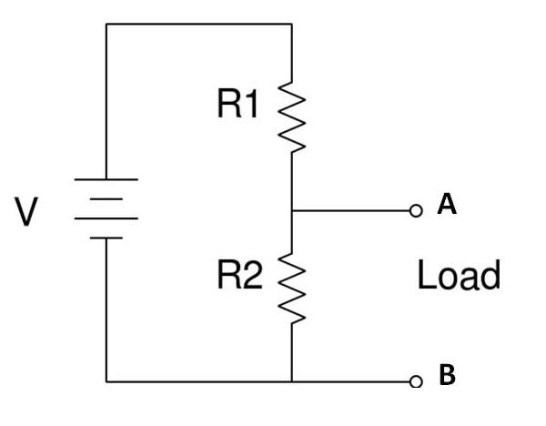
Figure 0.8: A standard voltage divider
3.1. First, build the voltage divider circuit, where R1 = R2. Measure the voltage drop across resistor AB. What is the relation between this drop and the output voltage of our power source? Place an LED in parallel with R2.
3.2. Now replace R1 with a resistor at least 10 times the value of R2. What is the voltage drop across AB now? What happens to the LED?
3.3. Now return R1 to its original value and replace R2 with a value 100 times bigger than R1. What is the voltage drop across AB?
As you have probably guessed by now, there is a linear relationship between the input voltage and output voltage, where the resistance is the slope. From our observations of the output voltage and the LED, we can see that when R2 >> R1, the output voltage is highest, and when R1 >> R2 the output voltage is lowest. The formula for a voltage divider circuit is the following: Vout = Vin * R2/(R1+R2).
Now that you know the basics of designing an electric circuit, it's time to learn basic Arduino/Teensy coding. Once again, if you already feel comfortable with any of the material covered, feel free to skip it.
In this section, we will review the basic building blocks of an Arduino sketch (the common name of an Arduino program), and work through several examples that will highlight these ideas.
First thing you have to do is familiarize yourself with the Teensy board. Please review this tutorial for a general overlay of the Teensy LC board. Although we may not be using the LC for our actual projects, understanding the LC board is key to understanding other Arduino/Teensy boards. Don't worry if you don't understand everything just yet.
Once you've familiarized yourself with the Teensy board, open up the Arduino IDE that you installed previously.
Every Arduino sketch has two main components, a setup and a loop function, as seen below:
The setup function runs once when you press reset or power the board:
void setup () {
  // code here
}
The loop function runs over and over again indefinitely:
void loop () {
  //code here
}
As seen in the comments, the setup function only runs once, and before any other code is run. The main purpose of this section is to initialize any global variables that might be used later, set up board pins for use (which board pin controls what), etc. The loop function is the main logic function of the Arduino sketch. It does exactly what you would expect it to - it loops! Generally, all the logic of the Arduino sketch is contained in this function.
Let’s quickly examine pins and writes in action. Head here and follow the tutorial there. You can find the code already written in your Arduino IDE by going to File>Examples>01.Basics>blink. The next segment will teach you how to load the sketch onto the actual Teensy board.
To upload a Arduino sketch from the IDE to the board, simply follow these steps once you have an Arduino sketch open:
-
Compile your Arduino sketch using the check mark button in the top toolbar. This will build your sketch code and check if there are any syntactical issues. If there are, you should fix them now.
-
Connect the micro-USB end of the USB wire into the board, and the USB end into your computer. If you completed the driver steps, your board should be recognized with no issues.
-
Go to Tools>Board and make sure you have the correct board specified. For this tutorial we are using the "Teensy LC".
-
Go to Tools>Serial Port, and make sure you have the correct board for your board selected. There generally is only one port, but if there are more, trial and error usually works.
-
If this is your first time uploading to the Teensy: click the Checkmark button in the toolbar and then press the pushbutton on the Teensy LC board.
-
Click on the Right Arrow button in the toolbar to upload your code.
The Arduino IDE uses a custom programming syntax known as INO, which is really just a derivative of C/C++. Because of that, the syntax in Arduino sketches is almost exactly the same is in C or C++ programs. The full supported syntax is listed out in the Arduino reference. Make sure you are comfortable with the structure section.
For coding projects in any language, but for INO specifically, you should be able to use:
-
if and if ... else statements
-
for and while loops
-
arithmetic operations
-
comparison operations
-
boolean operations
-
constants and variables
-
boolean, char, int, string and array data types
This is a lot to go through right now. If you have any prior experience with coding, then most of this should simply be looking up the new syntax. If you aren't familiar with these concepts, then don't try to go through all of the reference right now. Instead focus on the aspects that you think will help you solve a particular exercise as you go through this workshop.
Write an Arduino sketch to print "Hello World!". Make sure to use correct Arduino sketch layout.
Build on the following Arduino sketch so that it prints a 10-level left-aligned pyramid of asterisks. Make sure you use the variable levels in your loop function.
int levels;

void setup () {
  levels = 10;
}

void loop () {
  Serial.print("#");
}
Expected output:
#
##
###
####
#####
######
#######
########
#########
##########
Write an Arduino sketch that creates the following array {0, 1, 2, 3, 4, 5, 6, 7, 8, 9} using a while loop.
Functions are the building blocks for more advanced logic. Instead of writing all logic inside the central loop function, we can create functions to separate out logic, and simply call those functions within the loop. Not only does this help us keep track of the specific purpose of parts of our code, but it also helps us keep our code clean and manageable.
Writing functions in an Arduino sketch is identical to writing a function in any C program. Simply define the output type, the name of the function, and any inputs into the function.
int functionName  (int input1, char input2) {
  // . . .  logic here . . .
}
In the snippet above, we have a function called functionName with output type integer, and two inputs: an integer input1, and a char input2. As an aside, if you are familiar with C systems programming, you are probably used to dynamic memory allocation using the malloc() and free() commands, and returning allocated addresses. Arduino boards don’t have a heap, so you won’t be able to take advantage of that here. All logic should be done at the stack and global level.
Write a function that takes in two integers as input, and returns the integer sum of them.
Write a function that, when given a integer n, produces an array of with the first n Fibonacci numbers in it.
Call the first function in the second function so that after the Fibonacci array is created, the sum off all elements in the array is computed.
Write a function that takes a list of strings an prints them, one per line, in a rectangular frame. For example the list ["Hello", "World", "in", "a", "frame"] gets printed as:
*********
*Hello__*
*World__*
*in_____*
*a______*
*frame__*
*********
NOTE: Underscores represent spaces. Use a separate function for determining the frame width that takes in the list of words as an input and a separate function for printing a line of the frame, that takes in a word and the frame width.
As a final note, here are some links to documentation you may find helpful for configuring and using the pins of the Arduino (which also work with the Teensy):
For your reference, we have included a pinout diagram for the Teensy LC.
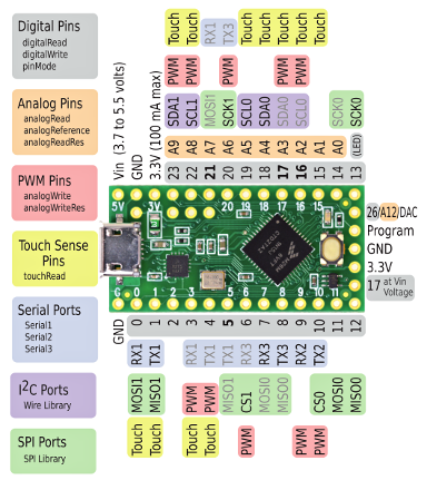
Figure 0.9: Pinout Diagram for the Teensy LC
For this final challenge you will merge the skills you've just learnt. But first you have to learned how to interface with the Teensy microcontroller. A Microcontroller both accepts and outputs current. There are designated pins in the Teensy which accept analog inputs or digital inputs (we will not delve into the details behind the differences). These inputs can then, with a little code, be used to control the output of the Teensy in such a way that we can output the right out amount of voltage to a target location (via a specific output pin). In this next exercise you will explore the magic of analog-digital interfacing. Such interfacing is essential in robotics, because most times robots need to be autonomous or controlled remotely, and a microcontroller like a Teensy can be programmed to control the circuitry in the way that we want it.
Read the following to know how to read from and write to an Arduino/Teensy pin:
For this challenge you should find one or two more participants to pair up with. You will be building a 3-bit binary counter. You will need the following components:
-
1 Microcontroller
-
3 LEDs
-
2 pushbuttons
-
Some resistors
The counter should use the 3 LED's to display the numbers 0 to 7 in binary (000, 001, 010, 011, 100, 101, 110, 111) and the 2 pushbuttons to either increment and decrement the count. You should code to protect against over and underflow (if the user tries to count to higher than 7 or lower than 0, the count should not change).
This challenge might prove to be quite difficult if you don't have a lot of electronics or coding experience. Don't hesitate to ask a HURC member for help. We're here to mentor you.