Welcome to the Harvard Undergraduate Robotics Club's Wintersession workshops! Over the course of these workshops, you will be constructing a miniature robot rover from the ground up. If at any point you have a question, don't hesitate to ask one of the HURC members for guidance.
That's fine! If you haven't used SolidWorks before, follow the steps below to complete an example project to gain some familiarity. If you are comfortable with Solidworks, skip to the next section.
-
Open SolidWorks by clicking on the appropriate icon on the desktop.
-
In the top left corner, start a new part by clicking "File -> New" or by clicking the white page icon in the top toolbar.
-
When prompted, select "Tutorials"
-
From the right hand bar that opened up, choose "Tutorials" from the "SOLIDWORKS Curriculum" section.
-
Choose "Lesson 1: Parts" and complete the tutorial.
-
Choose "Lesson 2: Assemblies" and complete the tutorial.
Now that you know how to work with Solidworks, it's time to design your robot's chassis! The design of the chassis is up to you, but there are a few things that you should keep in mind:
-
The servo motors we have aren't too strong, so you shouldn't make the chassis too big. We recommend making the chassis about as big as the HURC micromouse robot (ask one of the HURC members to show you the bot if you don't know how big it is).
-
Your chassis should hold 2 servo motors, 1 caster wheel, an Arduino UNO, a breadboard, a 9V battery and any sensors and other components you decide to use. Design a mounting solution for all parts!
-
The majority of the chassis should be built out of laser-cut acrylic. As such, your chassis should be buildable from 1 or multiple 1/4 inch flat acrylic pieces. We can also 3D print smaller non-flat parts for mounts. Ask the HURC members how to attach acrylic pieces to each other if you don't know how.
-
We recommend using 4-40 screws whenever possible. Ask the HURC members how big screw holes need to be for 4-40s.
-
Feel free to incorporate cool rastered designs into your chassis.
Please visit these URL's if you need datasheets on the components you will be working with: https://www.adafruit.com/product/64
https://www.adafruit.com/product/2442
https://www.adafruit.com/product/1200
https://www.adafruit.com/product/2744
https://www.arduino.cc/en/Main/ArduinoBoardUno
https://www.pololu.com/product/136
Once we have assembled the components of the robot, we need to connect them in a circuit that is controlled by a microcontroller, which is basically a computer without the operating system. For this project, you will be using an Arduino Uno programmed in the Arduino Programming Language (documentation here), which is essentially C/C++, but with some minor variations to tailor it for microcontrollers.
In order to upload programs to the microcontroller, you need to install the Arduino IDE. IDE is short for Integrated Development Environment, which contains not only the text editor we need to write our code in, but also a compiler to build our code, and communication protocols with the chip that we are programming. Arduino boards are small boards that contain a microcontroller and easy to use interfaces for programming the processor and using it to control electronics. Follow the steps below to get the Arduino IDE installed:
-
Click here to access the download page.
-
Download your appropriate installer, depending on what operating system your machine has.
-
Run the installer, and leave all options in their default states. Note: On Windows, you will get a pop up asking to install the Arduino USB Driver. This is very important, so click allow.
-
Once the install finishes, close the installer, and you should have the Arduino IDE installed on your computer!
Before you begin messing about with the Arduino, it is good to have an understanding of circuit theory.
The first thing you need to know before getting started are the components most used in electronic circuits, and how they work (at a very high level). The following are the components that you will need to know in order to begin building simple circuits (and, subsequently, simple robots). Figure 0.1 shows how a component is represented in a circuit schematic, and directly below are pictorial representations.
- Power sources - A power source provides the voltage (Volts) and current (Amperes) necessary to drive a circuit. At its core, it is a source of electric potential, and without it a circuit would be useless. Power sources can take the form of batteries, power supplies, or microcontrollers (an Arduino has pins for 3.3V and 5V out).
- Resistors - Resistors (Ohms), to put it simply, resist. They impede the flow of electrons through a circuit, and subsequently results in a voltage drop. A voltage drop is a change in the amount of voltage in the circuit, and through it one is able to control how a circuit behaves fairly accurately. One thing to know is that current always follows through the path of least resistance, thus if a current has a choice between a 500 Ohm resistor and a 10000 ohm resistor, it will flow through the 500 ohm resistor.
- Potentiometers (aka pots) - Potentiometers are essentially variable resistors. While a resistor can only have a fixed resistance, potentiometers can be tuned to any resistance within its range.
- LEDs - LED stands for Light Emitting Diode. In its ideal form, it turns current into light, while at the same time producing a voltage drop. Because LEDs are diodes, it is important to know that they only work if connected in the proper direction (the longer leg is the positive end, the shorter leg is the negative end).
- Capacitors - Capacitors act like buckets for electricity; they store charge and can thus be used as temporary and small batteries (as well as producing some other useful phenomenon). Some capacitors, like LEDs, are polarized and will only work if placed in circuit in the correct orientation (these will be clearly marked). Please make sure a polarized capacitor is plugged in correctly. They will explode if the polarization is reversed!
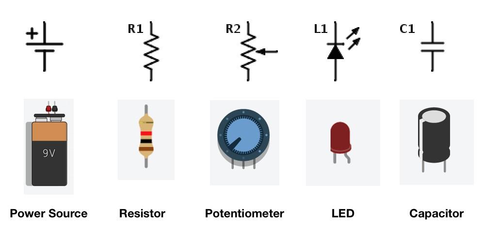
Figure 1.1: The components we’ll be working with
The next important step is learning the layout of the breadboard. A breadboard is a tool made for the quick prototyping of circuits. It is easy to build circuits, and fix mistakes because components and wires are stuck into the sockets of a breadboard rather than being soldered together permanently. Figure 0.2 shows the layout of an example breadboard. From the image you can see that if a breadboard is held vertically, the rows in the middle are connected together and essentially act as a single point. Similarly, the columns to the left and right of the breadboard are connected together. The rows are where you will be connecting most of your components and the columns are usually used for power and ground.
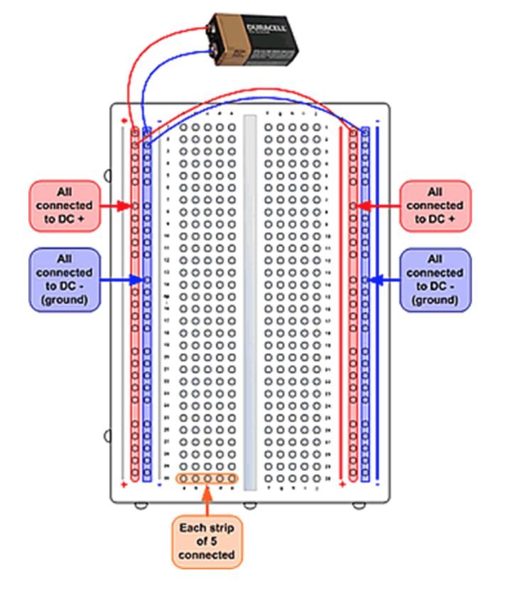
Figure 1.2: A standard breadboard
In this section, we will review the basic building blocks of an Arduino sketch (the common name of an Arduino program), and work through several examples that will highlight these ideas. Our main reference for this section will be the official Arduino reference, which can be found here. It is probably a lot to take in at once, but this page will probably answer any questions you might have about the syntax of the arduino language.
Ohm's Law is as follows: V = I * R, where V is voltage, I is current and R is resistance. In other words, The voltage drop across 2 points is proportional to the current flowing between those points and the resistance between the points. This formula (perhaps the most important in all of electronics) is extremely useful for most simple circuits, and for all the circuits being built today. The linear relation between V and I or V and R means that if we know any of the two values of a circuit, we can calculate all parameters that define how it works. We also have the power equation: P = V * I = I^2*R = V^2 / R, where P is power. The power value in an LED will determine how bright it shines and in a resistor, how much heat it will dissipate.
Looking at the schematic in Figure 0.3 you can see that the LED and resistor are in series in the circuit diagram. As you can see on the breadboard to the right, components in series need to share at least one row. The row allows for one component to conduct to another.
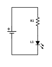
Figure 1.3: An LED and resistor in series
Looking at the schematic in Figure 0.4 you can see that the resistor and capacitor are in parallel in the circuit diagram. As you can see on the breadboard on the right, components in parallel need to share both rows as points of contact. When components share rows in this way, current must flow into both of them at the same time, this making the connection a parallel one.
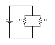
Figure 1.4: A capacitor and resistor in parallel
A multimeter is used to measure the V, I, and R -values at certain points in a circuit. Instead of using multiple separate devices, you can simply turn the dial on a multimeter to turn it into a voltmeter, ammeter or some other measurement device. The way multimeters measure voltage, current, and resistance are fundamentally different. A voltmeter must be placed in parallel to what you want to measure in order to find the voltage. An ammeter on the other hand must be placed in series with the circuit; the best way to do so is to pretend that it is another resistor. In Figure 0.7 you can see how a voltmeter and ammeter are placed properly in order to measure voltage or current. In order to measure the resistance of an element, you have to connect the multimeter in parallel to the component, similarly to how you would measure voltage.
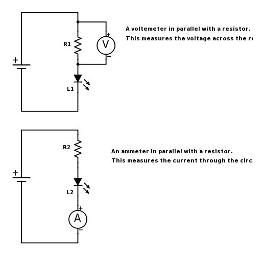
Figure 1.5: How to properly connect a voltmeter and ammeter
An important consequence of the voltage drop is that it can be used to control a circuit precisely. The so-called voltage divider circuit uses this phenomenon to create an output voltage of our choosing. See Figure 0.8 for an example of a generic voltage divider circuit.
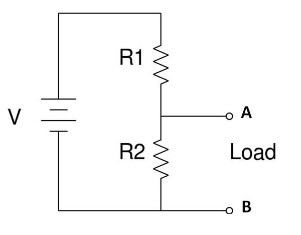
Figure 1.6: A standard voltage divider
The first thing you should probably do is review this tutorial for a general overlay of the Arduino Uno board. Don't worry if you don't understand everything just yet.
As mentioned before, the Arduino language is really just a derivative of C/C++. Because of that, the syntax in Arduino sketches is almost exactly the same is in C or C++ programs. The full supported syntax is listed out in the Arduino reference. Make sure you are comfortable with the structure section.
For coding projects in any language, but Arduino specifically you have to be able to use:
-
if and if ... else statements
-
for and while loops
-
arithmetic operations
-
comparison operations
-
boolean operations
-
constants and variables
-
boolean, char, int, string and array data types
This is a lot to go through right now. If you have any prior experience with coding, then most of this should simply be looking up the new syntax. If you aren't familiar with these concepts, then don't try to go through all of the reference right now. Instead focus on the aspects that you think will help you solve a particular exercise as you go through this workshop.
Every Arduino sketch has two main components, a setup and a loop function, as seen below:
The setup function runs once when you press reset or power the board:
void setup () {
  // code here
}
The loop function runs over and over again indefinitely:
void loop () {
  //code here
}
As seen in the comments, the setup function of the Arduino function only runs once, and before any other code is run. The main purpose of this section is to initialize any global variables that might be used later, set up board pins for use (which board pin controls what), etc. The loop function is the main logic function of the Arduino sketch. It does exactly what you would expect it to - it loops! Generally, all the logic of the Arduino sketch is contained in this function.
Let’s quickly examine pins and writes in action. Head here and follow the tutorial there. You can find the code already written in your Arduino IDE by going to File>Examples>01.Basics>blink. The next segment will teach you how to load the sketch onto the Arduino board.
To upload a Arduino sketch from the IDE to the board, simply follow these steps once you have an arduino sketch open:
-
Compile your Arduino sketch using the check mark button in the top toolbar. This will build your sketch code, and check if there are any syntactical issues. If there are, you should fix them now.
-
Connect the USB Type-B end of the USB wire into the board, and the USB Type-A end into your computer. If you completed the driver steps, your board should be recognized with no issues.
-
Go to Tools>Board and make sure you have the correct board specified. For this tutorial we are using the Arduino Uno.
-
Go to Tools>Serial Port, and make sure you have the correct board for your board selected. There generally is only one port, but if there are more, trial and error usually works.
-
Click on the Right Arrow button in the toolbar to verify and upload your code.
Write an Arduino sketch to print "Hello World!". Make sure to use correct Arduino sketch layout. This will be useful for debugging, as you can insert print statements in your code to check execution.
Build on the following Arduino sketch so that it prints a 10-level left-aligned pyramid of asterisks. Make sure you use the variable levels in your loop function.
void setup () {
  int levels = 10;
  Serial.begin(9600);
}

void loop () {
  Serial.print("#");
}
Expected output:
#
##
###
####
#####
######
#######
########
#########
##########
As a final note, here are some links to documentation you may find helpful for configuring and using the pins of the Arduino:
For your reference, we have included a pinout diagram for the Arduino Uno.
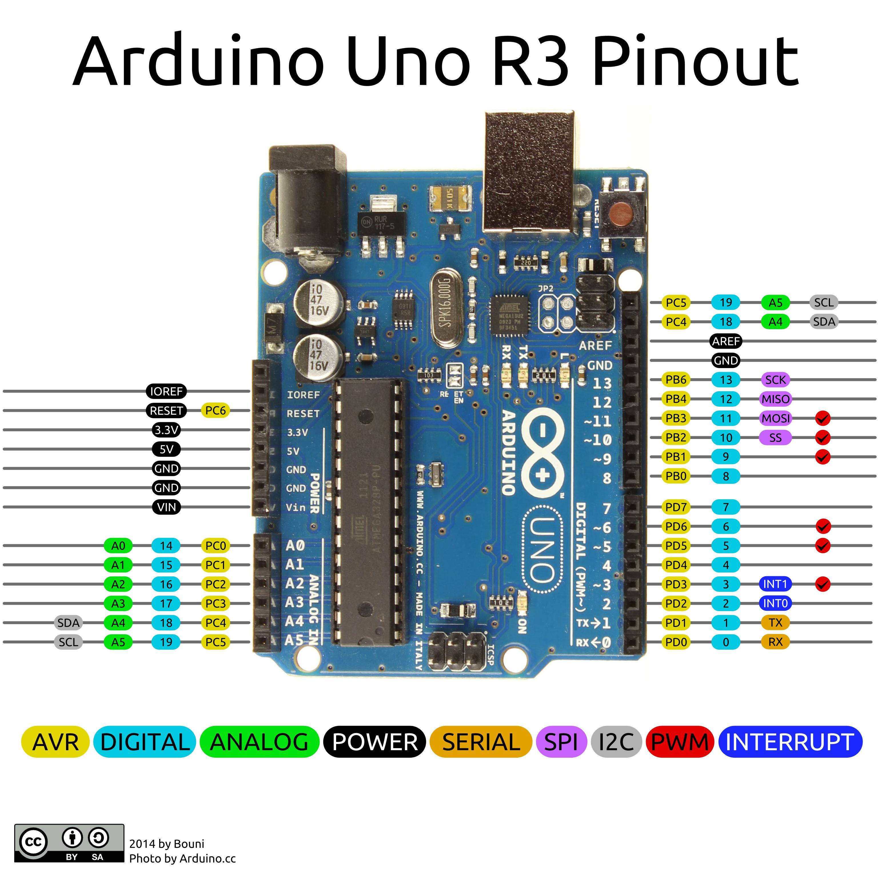 Figure(): Pinout Diagram for the Arduino Uno R3
For the robot, you will be using 2 small continuos servo motors. Continuos servo motors work very similar to regular motors, but offer a little bit more control.
Read this manual page to learn how to control the servo motor with an arduino.
The servos have 3 pins: Power, Ground and Control. Connect power (red) and ground (black) to the the 5V voltage regulator, which should be hooked up to the 9V battery. Connect control to an arduino output pin.
If your code or circuit doesn't work, then the first thing to do is to find out what is breaking. Try commenting out code or looking at parts of your circuit separately and testing if the individual components perform as expected. At first try splitting your code or circuit to 2-3 parts. Once you've detected the faulty piece, try recursively splitting into smaller pieces until you can pinpoint the faulty part.
Now that you have you have a chassis and know how to program an Arduino, assemble the chassis and start writing arduino code that will help you control the robot. At first try to make it move forward. Once you've managed that, try getting it to turn.
Having a robot rover that moves around according to your commands is pretty cool, but it would be way better if it could respond to its environment. If you have extra time, add a sensor to your robot! We will supply an assortment of sensors which you can attach to your robot to gain feedback from the environment. All of these can be connected to the Arduino for both power and communications.