Repository navigation

Replies: 4 comments 12 replies

|
SW mechanisms of those jobs and add_job function is not clear |
|
Here are the basic steps involved in an I2C request: The master device initiates communication by sending a START signal on the I2C bus. The start signal is a transition from high to low of the SDA (serial data) line while the SCL (serial clock) line is high. This signals the beginning of a new communication sequence on the I2C bus. When a start signal is sent, all slave devices connected to the bus will read the incoming address and data, and respond accordingly. The start signal is followed by the 7-bit slave address and a bit to indicate whether the master wants to write to or read from the slave device. The least significant bit (LSB) of the 7-bit slave address is used to indicate the direction of the communication. When the LSB is 0, it indicates that the master device wants to write data to the slave device. When the LSB is 1, it indicates that the master device wants to read data from the slave device. If the slave device is present on the bus, it will send an ACK (acknowledge) signal back to the master device.The ACK signal is a brief pulse of the SDA (serial data) line going low, while the SCL (serial clock) line is high. If the master device does not receive an ACK signal after sending a data byte to a slave device, it knows that the transfer has failed and can retry the transfer, send a stop signal, or take other appropriate action. If the master wants to write data to the slave device, it sends the data to the slave device. data is 8 bits long, and the ACK bit is sent after the 8th data bit has been received. Therefore, the ACK bit is an additional bit that follows the 8 data bits. ACK is sent after every data byte received. If the master wants to read data from the slave device, it sends a repeated START signal followed by the slave's address and a bit to indicate that it wants to read from the slave device. The slave device then sends the requested data back to the master device. master device can specify how many bytes it expects to receive from the slave device during a read request by sending an additional data byte called the "read request length" or "read command". The read command consists of a single data byte that is sent by the master device after the slave device has acknowledged the read request. The specific format of the read command byte can vary depending on the implementation of the I2C protocol, but typically the most significant bit (MSB) of the byte is set to 1 to indicate that it is a read command. The remaining bits of the byte can be used to specify the number of bytes to be read, or to encode additional information such as the register address or other control bits. Once the slave device receives the read command from the master device, it knows how many bytes of data to send in response. The slave device will then send the specified number of data bytes to the master device, and the master device will acknowledge each byte with an ACK signal until it has received all of the expected data. The master device sends a STOP signal to end the communication. The stop signal is typically represented by a "stop condition" on the bus, which consists of a high-to-low transition on the SDA (data) line while the SCL (clock) line is high. This is also known as a "negative edge" transition, since it involves the SDA line transitioning from a high level to a low level while the SCL line remains high |

|
The I2C 'state machine' (basically what you describe in above paragraph) is implemented in obc_i2c_int.c IRQ I2C_Handler(). You can see the start of i2c transmission in line 210..228. Reading the comment in line 210, I would interpret that you can make a job 'read only' by setting the dir (of the job structure= to 1! If you add 2 separate jobs, they are executed sequential without delay in between. To make some timing on job level, I would suggest to have this in the higher layers, but I think your EPU specification should be good with a single job only. (This code is almost original pegasus code and should work with PSU code ;-)) |
|
... that said (its Pegasus code based), I now remember, that we have occasional 'stuck communication' in OBC-EPU with pegasus flight software. Only workaround in orbit is to reset the OBC. So it is not said that the mentioned code is 'bug free'. During pegasus final tests EPU communication worked 'good enough' but no extensive stability tests where ever done then..... |

|
The original code used to work succesfully in the old flat bed setup. We assembled the new setup based on Flat-Bed PCB, and reflashed the comunication controller of the PSU. Now nothing works and we try to investigate. |
|
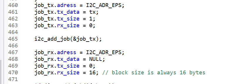
In the Pegasys code I see that we do set rx_size to 0 for the write request. And wise versa. Tx_size =0 when read request. I had a glance into I2C interrupt handler - yes it looks like it set the dirrection bit based on tx/rx_size (am I correct ?) |
|
ah wait no ...
The dir bit is set 0 (write) manually ????
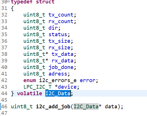
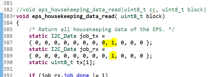
And in original PEgasys fuction it is set to 1 for both requests manually |

|
Yes, I think so. I am not aware if we changed this (tx-rx transition) between pegasus and climb. But if you tell me that you changed onl flatbed and PSU firmware and it broke, then I don't see any value in changing/analysing OBC-Code !? ;-) -> look for flatbed hardware and PSU software changes to get what broke it.... |
|
Yes exactly. It used to work with the old PSU setup. WIth new it does not. I did not change the OBC requests code. However it looks like the .dir was configured to be 0(writte) in the original pegasys request ???
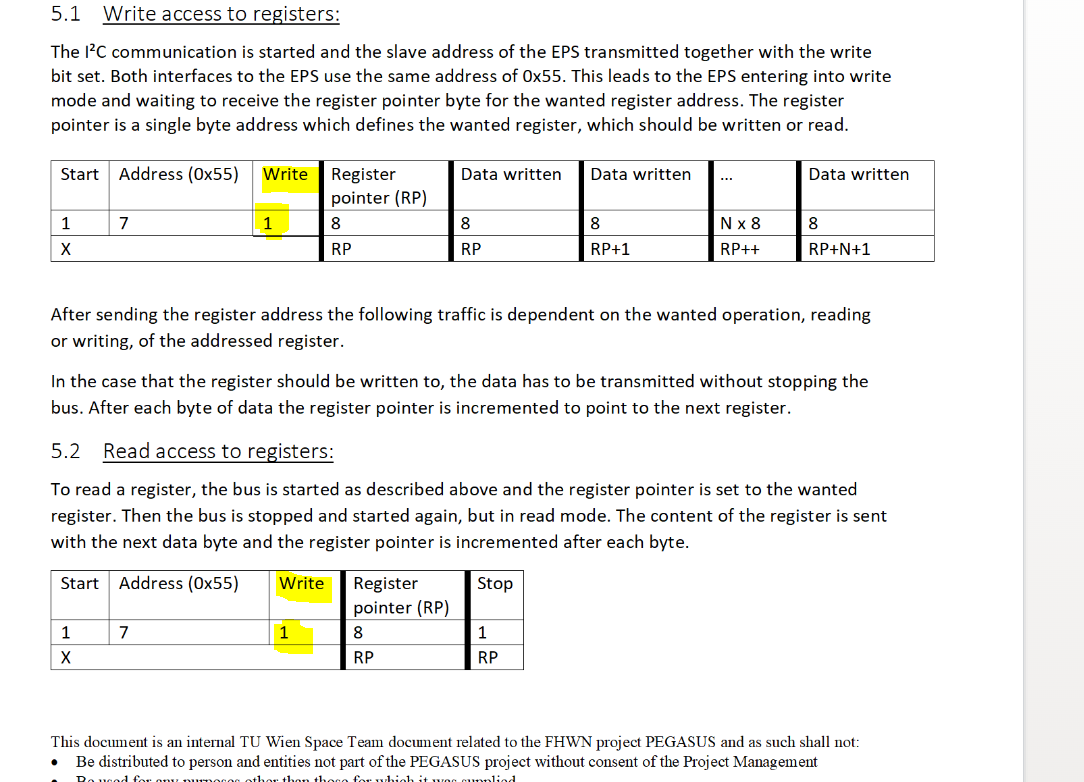
But the PSU document is completely misleading ???? The text in docu says - that there have to be 1) Write request (so dir=0) 2) Read request (so dir=1) but the tables with bit description are not in accordance .... |
|
I think, this I2C Master -> Slave procedure 1. Write Some bytes M->S and then immediate 2. read some bytes is pretty standard for master slave data transfer. |
|
On Tuesday session with Thomas Riel we reconnected PSU into the flat-bed and reflashed the PSU microcontroller. Since it does not work now - I again investigated into I2C com with test arduino :
I believe we will arrange another session on next Tuesday (correct ?) to try it out again with Thomas Riel ( who has the controll over PSU SW flash/debug). Hope it will work then.Yes it makes sense to change the PSU side so that it is able to implement the logics from one single request. The reasons why is it designed in such a way to require 2 separate requests are unknown to me. Need to discuss this with Thomas Riel |
|
In I2C 'language' there is no such thing as 'request'-'response'. Only the low level start/stop conditions used to enter the Rx TX mode on the Data line (Clock is always controlled by master). So the important thing here is If the occurrence of a 'new Start Condition with RX dir flag' is accepted by the slave to make the transition from TX (where the Slave already acknowledged the last byte with ACK) to initiate its RX sequence - where the Master has to ack all bytes then..... |
|
I am not aware of any tuesday sessions!? There was no meeting online this or last week - at least not to my knowledge..... |


Uh oh!
There was an error while loading. Please reload this page.
Need to implement a delay between adding the jobs (processing ??)for I2C.
Delay between write and read job should be implemented in accordance to cooperative multitasking. (what on an example is wrong)
All reactions