Show us your build ! #99
Comments
|
Brilliant 👍 I love this stuff 😁 |
|
My first build was similar, but I fried some components while experimenting with random wire antenna and grounding. The second one is a little bit tidier 😄 |
pictures or yours doesn't exist... you dissen my neatness bro?? |
|
This is my current build. I run out of toner transfer paper, so had to draw it using a sharpie 😮💨 |


|
Nice! Love the hand etched PCB 👍 |
|
|

|
Very neat! |
|
This is my projects setup. I'm adding RX amplifier, programmable step attenuator, low pass filter and LM386 speaker amplifier hardware. I'm also editing the existing code to include a menu for programmable step attenuator. |

|
Very cool, really like the step attenuator. How are you controlling it? |
|
This is my2nd build of Jon's picoRX. I'm using a pico2 with an external Tayloe decoder which allows me to mess with filter parameters. |

|
Nice work! |
Basically the relay controlling 3 attenuator base value which is 3, 5, and 10dB. From the combinations of this 3 value I can get an extra 10, 13 and 18dB. I'm adding 3 GPIO from Pico to control the relay via ULN2803. I modified your code with extra attenuator menu to select which attenuator value to used. This really help when I'm attaching my 20dB RX amplifier for strong signal attenuation process. |
Nicely done! Are you able to share your code? |
|
Attached are the code. Effected code are ui.h, ui.cpp, rx.h and rx.cpp. Yeah using i2c is the right choice to control it. |
Thanks! I got a shock when i diffed it against my working tree. |
Is there is any major update that improve the receiver performance on the testing branch? |
How does one build a attenuator? |
It can be as simple as 3 carefully chosen resistor values as described here. You could just pre-build some plug in modules of fixed attenuation and manually plug them in |
It is based on PI attenuator topology. To calculate it based on your need, please go to this calculator link: https://leleivre.com/rf_pipad.html |
|
Finally got around to ordering better parts and built a new analog board.
I forgot how fun SMD donut board work is: I've got enough room for an LNA but might need a 3rd board for band filters. Performance is somewhat better based on a simple reported signal level using a TinySA as a signal generator. Let me know if anyone wants me to do a comparison test of anything else before I recycle the old board... |


|
Have you tried to battery powering your board? I have noticed that USB power is quite noisy. Might just affect my build since I use a 5v powered switch. |
Yep - no perceptible difference from my laptop. |
Curious, I actually built-in a power-bank module into mine and I almost don't see a difference. I believe it's 134N3P-based. |
Where do you take your power from? directly from the battery or from the 5V? This module, Lipo Amigo Pro, should not produce any noise https://shop.pimoroni.com/products/lipo-amigo?variant=39779302539347 since it is taking the power from the battery almost directly, only going thru an battery protection circuit. |
|
I could not help my self, so I built a second one. This is my first Manhattan build.
Since I like woodworking I am also building a bookshelf shell for it with built in speaker. The shell is not ready for showing of just yet. |


|
As part of my build I made a minimal Pico Holder https://github.com/MrSVCD/PicoRX-accessories/tree/main/PicoHolder
|

|
So I am going traveling in a week and I can'd do that without a PicoRX. |


|
Finally done. |


|
Looks great 👍 |
|
Nice 👍 |
|
This PC Board designed by John Sutter, K6JDS, for the CalQRP Club includes a high pass BCI filter on the input, an audio amplifier and a lithium battery charger module. |

|
My first PicoRX has gotten a new home. I got a laptop charger connected for power and a LM317 & a 7805 for lowering the voltage down to reasonable levels for my antenna amp (12v) and the pico (5v). I had the parts laying around for this approach. @kp4md nice build. |

|
@kp4md Love the build. I have been following the calQRP builds, looks really good, love all the extra features! |
|
@dawsonjon Thanks for your work and inspiration! |
|
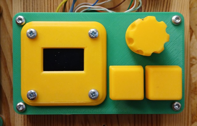
Upploaded the Contol Box as promised:
|
|
Very smart! |
|
Hello Jon, here is a picture of my prototype, I don't think it will the construction contest but it does work and should allow me to experiment with the hardware and firmware. Thank you for making this design available. Robert
|

|
@ROBFDP |
|
Although a prototype housing at this point in time with the next version incorporating a number of changes - just wanted to share the housing I designed to hold the CalQRP Club's project board of the PicoRx. I increased the size of the OLED and used the 1.3" variant. This seems to be a neat way of bringing all the components together. I'm very impressed with this little radio, great work Jon and other contributors .
|


|
@VK2ARH Nice work! That's a neat housing. I'm a big fan of the PCB sandwich style construction. Out of interest, what are the dimensions of the assembled receiver? |
|
Jon - thanks for the comments - the receiver is 100mm x 100mm. I'm currently working on a new 100mm x 100mm PCB with uses the basic layout concept of the CalQRP board together with its features (your brilliant design + BCI filter, LiPo Battery Charger, audio amp and speaker), but I have rearranged the position of the Quadrature Detector components and LNA, added a stepped attenuator 0,10,20,30dB (to prevent overload when tuning local AM stations), relocated the antenna input further up the side as well as the top (back) of the unit plus option provision for a BNC connector, have added a 7 pin connector for the external LCD screen, additional test points (for experimentation and fiddling) and three band buttons as shown on your schematic although I'm not sure if the firmware currently takes advantage of these. Boards have been produced and are in transit to me so looking forward to working with them although over the next couple of months there are likely to be more variants :)
. Some 3D images of the new board. |

|
@VK2ARH That looks very neat! I like the idea of a stepped attenuator! FYI, the band pins are actually outputs that can be used to switch filters. They were used in the original PCB version, but on the breadboard version I thought I would leave filtering to the discretion of the constructor, I left band control pins for backward compatibility. The band (filter control) outputs do still work, and you can program the band limits through the menu allowing up to 8 band filters to be selected. This could be a bank of 8 low pass filters (to remove QSD third harmonics) in a general coverage receiver, or you could have a band pass filter for each amatuer band in a more specialised receiver. |
|
Glad you commented - than now makes more sense ... Indicated that there are likely to be more variants :) - I think the next iteration will look at disabling the incoming antenna signal when a Tx signal is detected to enable the unit to be used with 'companion transmitters'. Oh the fun continues. |
|
@dawsonjon I already pull your latest code and patch the code with my attenuator and RF switch (for filter selection) functionalities. I'm also integrate it with TFT screen and finally got the model which you previously suggested. The result was very good, very thanks to you and your team for a great improvements. 9M2GRC - 7 3 Video on 40m: https://drive.google.com/file/d/1BPVP3ASSt92c-Rr9QGedGOUElRarHw4j/view?usp=sharing Picture of my build:
|

|
@dawsonjon One question, do you still maintain 12KHz (+6 and -6KHz) bandwidth on your Tayloe detector calculation? Correct me if I'm wrong, the RF spectrum bandwidth is it 30KHz? |
|
@bahari Nice build! The Tayloe detector has a cutoff of +/-12kHz, and I use an IF of +6kHz or -6kHz. That means that the 3dB bandwidth is 24kHz and the spectrum displays 30kHz, so you can see the gain dropping off at the edges. |
|
@dawsonjon I noticed on the RF spectrum and it is consistent, in one occasion I can see there is RF detection at the positive side of the RF spectrum TFT screen, but when I increase the frequency tuning, it is disappeared and the RF detection goes to the negative side of the display, do you observed the same? |
|
Yes, that't because it chooses an IF of either +6 or -6kHz, the signal you
are seeing is noise around the NCO frequency/DC.
…On Sun, 9 Feb 2025 at 17:13, bahari ***@***.***> wrote:
@dawsonjon <https://github.com/dawsonjon> I noticed on the RF spectrum
and it is consistent, in one occasion I can see there is RF detection at
the positive side of the RF spectrum TFT screen, but when I increase the
frequency tuning, it is disappeared and the RF detection goes to the
negative side of the display, do you observed the same?
—
Reply to this email directly, view it on GitHub
<#99 (comment)>,
or unsubscribe
<https://github.com/notifications/unsubscribe-auth/AAFPFX7R77AMSOY76JTJQN32O6ECXAVCNFSM6AAAAABPDD4XZOVHI2DSMVQWIX3LMV43OSLTON2WKQ3PNVWWK3TUHMZDMNBWGQYTKOJTHE>
.
You are receiving this because you were mentioned.Message ID:
***@***.***>
|
|
@dawsonjon Today I also discovered there is RF detection on the positive side of the RF spectrum (around 18,000KHz ++), when I tuned it to the center, It's suddenly shifting to negative side of the display (near center) and I can hear the audio modulation. But when I tried to centered it, It suddenly disappeared and goes to positive end of the display. |
|
I find this a really cool use of a Pico. A quick question regarding the analog-switch/mux. The 74CBTLV3253 is suggested. Why would a CD4052 not be suitable? Too slow? R-on too high? I am wondering if there is a suitable replacement for the mux that is available in a DIP package. For example, why not a SN74LV4052AN or TC74HC4052APF? |
Mostly because its too slow. Its higher R-on doesn't either. I think you'll have to get comfortable with DIP/SMD adapters. They're cheap enough on ebay AliExpress and I see imsai_guy has produced some nicer looking skinnier boards for SOP packages on pcbway. |
|
Thanks for pointing me to your sensitivity graph. It explains the situation nicely. |
|
Instead of the 1:4 mux 4052 use a 4053 dual 1:2 mux as QSD
With the 1:4 mux, each switch is only one quarter of the period on and three quarters off. With the 1:2 mux, each switch is on and off for half a period, which results in longer switch-on times. A 74HCT4053 with +5V Vcc works up to at least 30MHz, some even up to 54MHz (6m). A 74HC4053 with +5V Vcc switches significantly slower with the (low voltage) TTL quadrature clocks of the RP2040. Compared to a QSD with a 1:4 mux, the circuit with two 1:2 mux has a 2dB higher conversion loss. This can be compensated by using instrumentation amplifiers for the baseband signal instead of simple differential amplifiers. |

|
@Frank-663 Thanks. This is an interesting alternative. I appreciate it. |
|
I made an SMD version of the PicoRX. The PCB size is the same as the Pi Pico, so it has a very small footprint. All of the digital circuitry is on the bottom side of the PCB (it's pretty packed down there). The top side includes a 7th order Chebyshev low pass filter with a cutoff at 30 MHz. There is a header for connecting a headphone jack to listen to the audio. Four layer board. It makes for a cool little pocket shortwave receiver (controlled via laptop), FT8 receiver, etc.
|

|
@SyncChannel Very cool build! Did you have any plans to share the design? I'm sure there would.be a lot of interest. |
|
@dawsonjon I uploaded the KiCad files here if anyone is interested. I don't have time to do extensive documentation on it right now, but the PCB files should be enough for anyone to re-create it if they want to. https://github.com/SyncChannel/PicoRX-SMD I made a similar board for your Pi Pico Transmitter project, it works quite well! |
lovely, can you also please share details of the Tx part. Do you have a video of the Rx in action ? |
No matter how modern, steampunked or deviated from the recommended design :)
I'll kick things off...
Mine has a few substitutions based on what was to hand:
TL072 for the opamp
74HC4052 scavenged from a Pace set top box :)
The four tayloe caps are 27nF cos the 74HC4052 has a higher Ron
Small proto area that I can use for band low pass filters (the green wire.
This board runs at 5v so there's a pair of 1.8k/3.3k resistors to drop the amp outputs to 3.3v max
No preamp.
Its good for about 10MHz, FT8 on 14MHz is buried in noise.
Local AM stations are fine on an old skool wire loop antenna and some will totally overload the radio when on my EFHW.
The EFHW works well for 40m stuff.
Top view with SH1106 and buttons - the 2 boards could be folded back to back

Close up of the RF front end board

And some pretty average soldering...

The text was updated successfully, but these errors were encountered: