Examples
The examples folder contains examples from the Arduino world that are can be used directly with PiDuino. The only thing to add is the line:
#include <Piduino.h>Here is the source code of the example Blink that flashes a led:
#include <Piduino.h> // all the magic is here ;-)

const int ledPin = 0; // Header Pin 11: GPIO17 for RPi, GPIOA0 for NanoPi

void setup() {
  // initialize digital pin ledPin as an output.
  pinMode (ledPin, OUTPUT);
}

void loop () {
  // Press Ctrl+C to abort ...
  digitalWrite (ledPin, HIGH);  // turn the LED on (HIGH is the voltage level)
  delay (1000);                 // wait for a second
  digitalWrite (ledPin, LOW);   // turn the LED off by making the voltage LOW
  delay (1000);                 // wait for a second
}
Obviously, you need to know the pin number where you connected the LED !
This number depends on your model of Pi board, to know it quickly, we can type
the command pido readall 1, which gives us, for example, the following display
on a Raspberry Pi B:
                                    P1 (#1)
+-----+-----+----------+------+---+----++----+---+------+----------+-----+-----+
| sOc | iNo |   Name   | Mode | V | Ph || Ph | V | Mode |   Name   | iNo | sOc |
+-----+-----+----------+------+---+----++----+---+------+----------+-----+-----+
|     |     |     3.3V |      |   |  1 || 2  |   |      | 5V       |     |     |
|   2 |   8 |    GPIO2 |   IN | 1 |  3 || 4  |   |      | 5V       |     |     |
|   3 |   9 |    GPIO3 |   IN | 1 |  5 || 6  |   |      | GND      |     |     |
|   4 |   7 |    GPIO4 |   IN | 1 |  7 || 8  | 1 | ALT0 | TXD0     | 15  | 14  |
|     |     |      GND |      |   |  9 || 10 | 1 | ALT0 | RXD0     | 16  | 15  |
|  17 |   0 |   GPIO17 |   IN | 0 | 11 || 12 | 0 | IN   | GPIO18   | 1   | 18  |
|  27 |   2 |   GPIO27 |   IN | 0 | 13 || 14 |   |      | GND      |     |     |
|  22 |   3 |   GPIO22 |   IN | 0 | 15 || 16 | 0 | IN   | GPIO23   | 4   | 23  |
|     |     |     3.3V |      |   | 17 || 18 | 0 | IN   | GPIO24   | 5   | 24  |
|  10 |  12 |   GPIO10 |   IN | 0 | 19 || 20 |   |      | GND      |     |     |
|   9 |  13 |    GPIO9 |   IN | 0 | 21 || 22 | 0 | IN   | GPIO25   | 6   | 25  |
|  11 |  14 |   GPIO11 |   IN | 0 | 23 || 24 | 1 | IN   | GPIO8    | 10  | 8   |
|     |     |      GND |      |   | 25 || 26 | 1 | IN   | GPIO7    | 11  | 7   |
+-----+-----+----------+------+---+----++----+---+------+----------+-----+-----+
| sOc | iNo |   Name   | Mode | V | Ph || Ph | V | Mode |   Name   | iNo | sOc |
+-----+-----+----------+------+---+----++----+---+------+----------+-----+-----+
The iNo column corresponds to the 'Arduino' number, the number 0 pin corresponds therefore at pin 11 of the GPIO connector (GPIO17).
To compile the blink program on the command line, you must type the command:
$ g++ -o blink blink.cpp $(pkg-config --cflags --libs piduino)
The last part of the command uses pkg-config to add the build options to g++
in order to compile the program correctly.
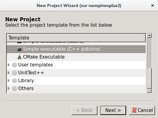
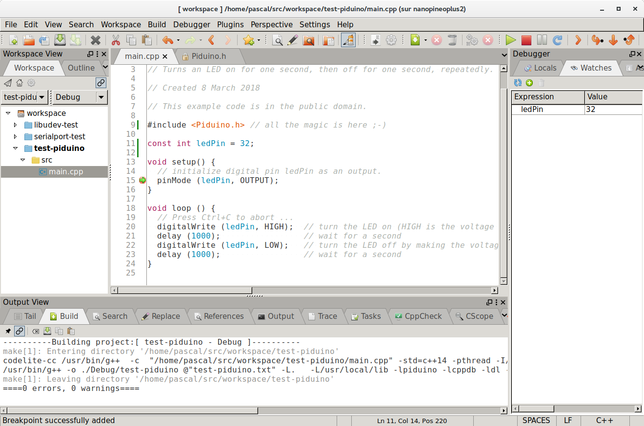
To have a more user-friendly development environment, it is advisable to use Codelite, the installation of PiDuino adds a program template for PiDuino:
In Codelite, one can not only compile, but also edit and especially to debug the program:
the second example rtc_bq32k, uses the Wire library to read the time in a BQ32000 RTC circuit.
It allows to discover 2 important differences between an Arduino board and a Pi board:
- First, on a Pi board, the human-machine interface (screen and keyboard) is done on the command line (the console !). On Arduino, the serial port is used.
- On a Pi board, a program can finish to give the user a hand. On Arduino, the program never stops (in fact on a Linux system, the kernel program never stops either...)
To solve the first problem, PiDuino defines a Console object whose
the usage is identical to the Serial object (it is a class derived from Stream).
In order to allow compilation on both platforms without modifying the source code,
we can add at the beginning of the sketch a block that tests if the target platform is
a Unix/Linux system (PiDuino), if so, the inclusion of the file
Piduino.h is done, otherwise we define a Console alias which corresponds to
Serial, ie the human-machine interface is on the serial port.
#ifdef __unix__
#include <Piduino.h>  // All the magic is here ;-)
#else
// Defines the serial port as the console on the Arduino platform
#define Console Serial
#endif

#include <Wire.h>

void printBcdDigit (byte val, bool end = false) {
  val = (val / 16 * 10) + (val % 16); // BCD to DEC

  if (val < 10) {
    Console.write ('0'); // leading zero
  }
  if (end) {

    Console.println (val);
  }
  else {

    Console.print (val);
    Console.write (':');
  }
}

void setup() {

  Console.begin (115200);
  Wire.begin(); // Starting the i2c master
}

void loop() {

  Wire.beginTransmission (0x68); // start of the frame for the RTC at slave address 0x68
  Wire.write (0); // write the address of the register in the RTC, 0 first register
  Wire.endTransmission (false); // restart condition
  Wire.requestFrom (0x68, 3); // 3-byte read request

  if (Wire.available() == 3) { // if the 3 bytes have been read
    byte sec = Wire.read();
    byte min = Wire.read();
    byte hour = Wire.read() & 0x3F; // remove CENT_EN and CENT LSB bits

    // time display
    printBcdDigit (hour);
    printBcdDigit (min);
    printBcdDigit (sec, true);
  }
  exit (0); // exit the loop() function without ever coming back.
  // On Arduino, exit() performs an infinite loop as explained on
  // https://www.nongnu.org/avr-libc/user-manual/group__avr__stdlib.html
  // on a Pi board, exit () stops the program by returning the supplied value.
}
To solve the second problem, it is possible to use on the 2
platforms the exit () function (which is defined in the
standard library).
This function, compatible with both platforms, allows to stop the execution
the loop () function.
On a Unix / Linux system, it stops the program and returns to the command line, on Arduino, it performs an infinite loop (after calling the destructor of C ++ objects).