Problem with setWatch on MDBT42Q #3234
Replies: 17 comments
-
|
Posted at 2020-01-02 by Robin Thr 2020.01.02 Hi @oscar, thank you for your interest in this exciting world with Espruino! Haven't worked with a capacitive touch sensor, and am on lunch break, so not a lot of time on this end as I'll need to get back to the salt mine shortly. Will have time later this evening. Will need to determine the internal resistance for 'pulldown' mode. Has a different pinMode been tried? Pin D28 is also an ADC. Possible conflict with that mode? Try a non ADC pin comparrison. Does setWatch() read analog pins? Would analogRead() be a better choice? L1 is only used once. How is the 3.3v input test being performed? A working example: In the mean time, would you please post links to datasheets, page references that pertain to wiring, I/O, I2C, examples etc. and also Try searching google with the site keyword qualifier:
|
Beta Was this translation helpful? Give feedback.
-
|
Posted at 2020-01-02 by Oscar Digital-only PIN or ADC pin - both tried as digital with no difference. I guess I could avoid the problem entirely using setInterval instead of setWatch and figure an interval that would feel quick enough to catch all "touches". In that case I would use analogRead(D28) > 0.5 as "high" and my problems would go away. 3.3V input test: I connect D28 to the 3.3V pin of the board or the input pin of the touch sensor (the sensor is fed by the 3.3V pin of the board). |
Beta Was this translation helpful? Give feedback.
-
|
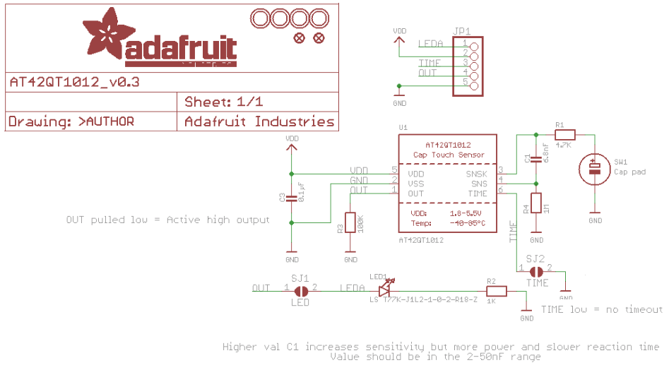
Posted at 2020-01-02 by @allObjects @oscar, I assume you did the basic test with the sensor (break out board) as well as you did with your code. I worked through the specs of the touch breakout board as well as thru the chip's data sheet and I see no glaring thing. If the sensor is doing its job - its LED comes on and goes off on touch - either momentary or toggling - I can only think of some wiring issue or issues with the output... If you have a multi meter, measure what is going on with the touch sensor output (according to schema, it has a 100K GND connected pull down resistor and it is acktive high, you need to set the Espruino pin to "input" only... no need for an extra pull-down. Also, you do not really need a debounce, since it that is taken care of by the chip... except you want to impose an extra behavior).Attachments: |
Beta Was this translation helpful? Give feedback.
-
|
Posted at 2020-01-02 by Oscar Yes, I tested the touch sensor with a multimeter. When touched, the voltage between OUT and GND is just slightly lower than between VCC and GND (all around 3.3, 3.2V). And that appears to be the problem! I've also tried the same wiring replacing the touch sensor with a regular mechanical push button and the initial code works. |
Beta Was this translation helpful? Give feedback.
-
|
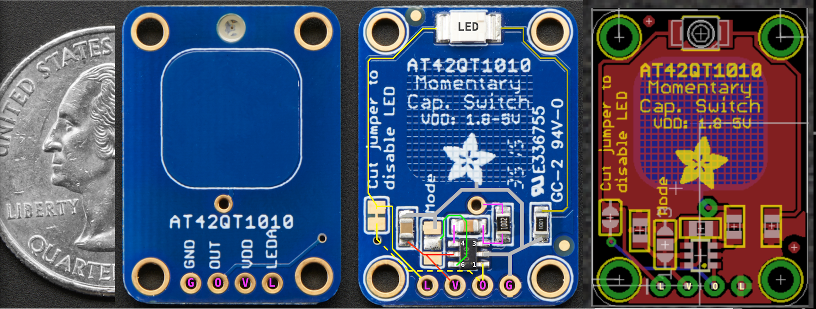
Posted at 2020-01-02 by @allObjects Do a visual inspection of the touch breakout board for some sort of short cut. Give connecting the onboard LED a shot... connect the SJ1 solder pads. If the LED is constantly on, then something in the input circuit is messed up or the whole thing is in lala land. Usually, software is the primary issue... but here, I feel safe to say: it is the hw... since you tested w/ electro mechanical switch and validated your software. Can you pub a focused, really close-up shot of the thing - for comparison w/ below one? Attachments: |
Beta Was this translation helpful? Give feedback.
-
|
Posted at 2020-01-02 by @allObjects Comparison shot and schema show differences... in number of components (resistors) as well as values... But nice of this this breakout board design it that - when solder jumper SJ1 (LED) is cut, LED can be controlled / reused externally... - thinking now about the reaction game with multiple sensors with LEDs turning on randomly and have to be turned of by touching as quickly as possible... (and: @drazzy: non-wearing pin ball exit lane sensor! ...worth a try... never heard back from @matencio ...) |
Beta Was this translation helpful? Give feedback.
-
|
Posted at 2020-01-03 by Robin
Wouldn't a hall effect transistor detecting the metal ball be a better option?
and after all that work! Prototype, 300 lines of code, pics, vids, a fully working example handed to him to boot. After (circa end of Feb) a week of no response to his PM, I made the assumption that the two of you were working together off forum to complete his project. Not a total loss @allObjects as I learned some coding techniques! Maybe use for the next Espruino Instructables feature? |
Beta Was this translation helpful? Give feedback.
-
|
Posted at 2020-01-03 by Robin Thr 2020.01.02
Shouldn't this be the 'output' pin of the sensor? Which 'board' is feeding the 3.3v? Are both boards securely grounded to each other?
As I look over the schematic and datasheet, that is what should be seen. What is the voltage between OUT and GND when no object is on the sensor pad?
By initial code, are we still referring to the snippet in #1 post? There is only one usage L1 of the digitalRead() statement, which really isn't needed, except maybe to test. Is the test then, . . . placing a finger on the sensor, then upload the code to the MDBT42Q? Looking for a 'rising' edge when a pull down is specified inside the setWatch() most likely won't work as the pin is always grounded. How is the mechanical switch connected and what value of external resistor is used? Replacing the input with a mechnical switch, when used as described in the last sentence, may provide a false observation. Just shorting the the input pin, will force the use of the internal pull-up/down, depending on the pinMode() setting, which was mentioned to have changed. Also, L2 setting the pinMode() after, actually should occur before the read event. Your idea #3 post of using a setInterval() has merit, but use a digitalRead() inside. Call pinMode() with 'input' as pointed out in #4 post. The 100K pull down on the cap sensor output won't have an effect on the 13K input pull up (p.151 Rpu nRF52 datasheet) as that output is sourcing high. |
Beta Was this translation helpful? Give feedback.
-
|
Posted at 2020-01-03 by Oscar Both boards (MDBT42Q and Adafruit touch sensor) have common ground. Voltage between Vcc and GND on the touch sensor is 3.3V (as expected). This OUT voltage gets sensed as HIGH on my other microcontroller boards using CircuitPython and 3.3V logic. However, then connecting OUT to pin D25 or pin D28, touching the sensor (thus 3.22V) and having said pins pulled down (L2 of snippet1), digitalRead(pin) returns 0. In the case of D28, I can also try an analogRead(D28) and it returns 0.97, which means that the pin "sees" the voltage. In summary: Is this expected? Answers to #9: Thanks again for all the replies! |
Beta Was this translation helpful? Give feedback.
-
|
Posted at 2020-01-03 by Oscar Well guys: I did a hard reset of the board, erased the saved code, did not physically change anything on the circuit but it is now working, that is, digitalRead can sense touches on the board. I have no idea what helped but thanks again for all the inpu! Oscar. |
Beta Was this translation helpful? Give feedback.
-
|
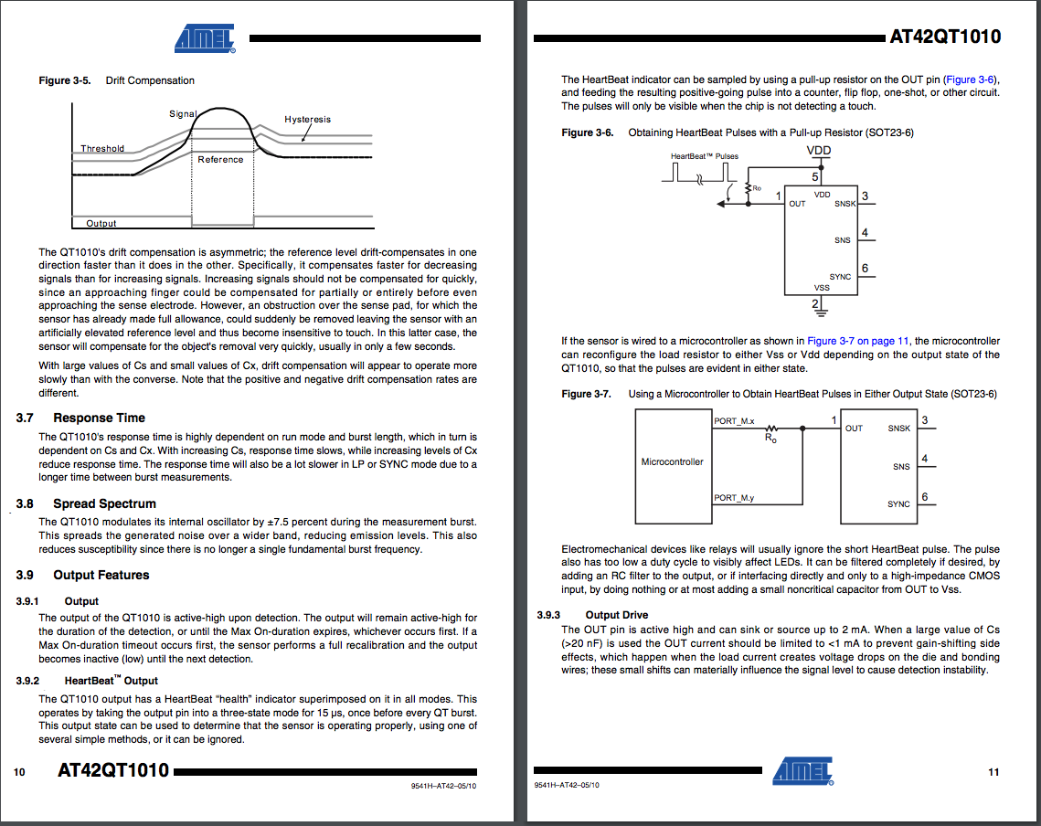
Posted at 2020-01-03 by @allObjects @oscar, I read something about the heart beat the AT42QT1010 can send out... and that could have messed with you... The data sheet says that the heart beat is not strong enough to make an LED lite up to be noticed by naked eye and and it can be filtered out w/ (capacitive) load... Since I have seen different board population and the option of being able to have the LED connected or not, this could also have contributed. For what ever reason this heart beat could have confused the readings and explains why the analog read always almost HIGH (3.22 vs 3.33). In addition, I said that you do not need a pull-down (on the input side) because the schema showed a pull-down on the out-put but the board does not have one, the heart beat could create this confusion. See https://cdn-shop.adafruit.com/datasheets/AT42QT1010.pdfhttps://cdn-shop.adafruit.com/datasheets/AT42QT1010.pdf pages 10 and 11 (pages attached)... - Why though without change of circuitry and only clearing software on the MDBT42Q fixed the issue... not much other than on the init before somehow the wire / pin got loaded with initial high the capacities and something else held them high enough for the analog to read something where as the regular input did not fire... the debounce did not help either here: it could have consider the heart beat as bouncing... No matter what, you got it going... and having a
|
Beta Was this translation helpful? Give feedback.
-
|
Posted at 2020-01-04 by Robin Fri 2020.01.03
@oscar, it was mentioned that setWatch() and setInterval() were being used for testing. Could it be that code snippets (after each test) were being uploaded on the Left-hand Console side, after at least one upload of an existing code file, using the Right-hand editor side? my comment will be based on the response |
Beta Was this translation helpful? Give feedback.
-
|
Posted at 2020-01-04 by Oscar @robin, the calls to setWatch() and setInterval() were uploaded from the right-hand editor side. For testing, I used individual calls to digitalRead() and analogRead() from the console (left-hand side). |
Beta Was this translation helpful? Give feedback.
-
|
Posted at 2020-01-04 by Robin Sat 2020.01.04 Thank you @oscar I use that same code/test ritual also. One question I forgot, which PC OS are you running with? Most here seem to use Linux or a variant, I am running Windows10. I'm posting the following observation more to inform @gfwilliams and the Espruino project masters, and to determine if there is common denominator, e.g. device type, developer coding/testing practice, WebIDE, PC OS issue, other. > recap - may jump ahead to bold heading and come back if necessary I had what I filed under bizzare issues when using a Pico on a previous HP Notebook laptop running Windows10 which I had successful coding for web development C# HTML and Javascript with all major browsers, for several years. The first started around July of 2017 which I thought was the WebIDE as updating did occur for a while, but this may have been BLE as it was in the early stages for Windows10. Then in Sept of 2018 which we did resolve as being an issue with how the WebIDE used relative paths within Windows10 when that OS uses the \documents folder for saved app locations along with Then in July of 2019 a Windows10 update nightmare and recently, while undocumented on this site, another, the 2nd 'Blue' screen of death (not 'Black' screen) on my new Asus screamer RAM drive laptop while leaving my laptop on overnight, updates as 'download only install by user' enabled, auto rebooted leaving just the 'Blue' screen visible. So in my case, as we now had a second PC involved, different hardware, different BIOS, version difference in OS, but version change in WebIDE and many updates/changes with Espruino, I thought that it was more to do with Windows10. *(up until a month ago)* Recently in Oct 2019 the perceived bricked MDBT42Q After finally getting Espruino back on to that device, AND AFTER the latest Windows10 upgrade started noticing some really bizarre behavior. The only recovery means after lockup I've been able to preform is to:
This is on a new mfg six month old Asus with internal BLE running Windows10. It is an absolute royal pain when the following does occur, as the sequence to get re-started is time consuming. ***Now the interesting part and how it relates to @oscar and this thread*** A common device, the MDBT42Q and common Javascript functions. My coding/testing method is, and most likely is what most of us do in fact do, that we write code in the WebIDE Right-hand editor side and save the file for easier/quicker future upload. We then test and add future snippets by either typing directly or block copying into the Left-hand console side. I started to notice that when using I used to use But WAIT there's more . . . My recent Aug 2019 struggle with getting @gfwilliams 's functioning code to work on my platform:
. . . and, . . . In this thread, @oscar made several comments regarding unusual anomalies, that when re-read, do in fact make one wonder if Mother Nature or Physics is not as we really understand it. Experience and common sence however, lead us to understand that there is a common denominator, just have to find it.
I have discovered that under some circumstances, it is possible to place the device in a state that is un-recoverable and, as @oscar also found out, leads to unbelieveable and bewildering troubleshooting also. It appears the only recovery is to get rid of all uploaded code, and start fresh as in his #11 post. One of which is not fully remembering that a timer is running when attempting to re-send the exact code a second time. That could be considered a developer fubar, but what about the condition where the WebIDE locks up? I got burned on this, when I disconnected the WebIDE and reconnected, making the false assumption the board would restart. It wasn't until many hours later, and after remembering the snippet below, that I would discover many timers running, and even after using The other is as @oscar found out that when both are saved into flash, that even attempting to upload them, won't change the underlying behavior. But, as we have learned in this thread here, one has to discover this fact. To Oscar it appeared as if a digitaRead() wasn't working as defined, when in fact it most likely was one of the other items, causing the mis-behavior. Found this in the forum for others and specifically @oscar to see whether timers are running: Is there a similar means to see whether watch's are running? ***Observations:*** * Over the last year have noticed forum postings on users having connect/dis-connect issues * Common denominators MDBT42Q, setWatch(); setInterval();
* Left-hand console copy of identical code not always reliable *(setWatch(); setInterval();)*
* Now documented, TWO independent developers using similar adopted code/test technique
While I'll file this as an anomaly that occurs when copying identical code into the Left-hand console side, when that code currently resides in RAM (and possibly ROM; save();) it is an issue that others may trip into, I still wonder if there is an underlying process that isn't working quite right or up to par. |
Beta Was this translation helpful? Give feedback.
-
|
Posted at 2020-01-04 by Oscar I use macOS. |
Beta Was this translation helpful? Give feedback.
-
|
Posted at 2020-01-04 by @allObjects never ever save() with timers or connections going... put all of your real startup code in the onInit() function... most of this classic conversation about simple explanation how to save code that Espruino run on start? is still true to the day... and if considered, saves hours... therefore: when thinking about save(), save yourself hours by sticking with some basic parameters (when it comes to timers and watches... BLE connectivity is a bit different...) |
Beta Was this translation helpful? Give feedback.
-
|
Posted at 2020-01-04 by Robin Sat 2020.01.04
Thanks again @allObjects for that sage advice. I adopted and have been using that technique for over a year. I do find that comment a bit odd and out of place as I never mentioned the use of save() during my development, nor did @oscar even bring it up until #11 post. While that may have been contributory in @oscar 's case, we all missed that, nor did any of us consider that possibility. We all wasted a ton of time chasing a ghost! I only point out #15 Observations as I got burned on the same task again today, with multiple timers and set watches, even knowing that their use was problematic! While it is possible to over write a variable with a new value, and Espruino is acceptable at (seems to be always) over writing functions (even after a save();) with a unique new definition, there are issues as I pointed out with specifically those two functions. I even had an issue where using a global var to accept the ID of an interval, did not get cleared with |
Beta Was this translation helpful? Give feedback.
Uh oh!
There was an error while loading. Please reload this page.
-
Posted at 2020-01-02 by Oscar
Hi,
I'm just getting starting with Espruino and I'm new to the setWatch function.
I have a MDBT42Q board that I want to read a button input from a capacitive touch sensor momentary switch from Adafruit (https://www.adafruit.com/product/1374). The code is as follows:
If I connect briefly D28 to the 3.3V pin it works as expected.
But if I connect it to the output of the momentary switch (and I touch the switch) it doesn't.
I played with the pin D28 as an analog input and I have observed the following:
D28 reads 0.99 when connected to the 3.3V pin.
D28 reads 0.97 when connected to the output of the switch (and the switch is touched). This corresponds to around 3.22V.
D28 reads close to zero when the switch is in open position (no touch).
All results make sense and in analog mode I can read the sensor being touched.
But it appears that the setWatch function interprets in digitalRead mode 0.99 as high but 0.97 as low, as if the threshold for a high would be beyond 0.97.
Is this an expected behavior? Can this threshold be changed? I would have expected that anything beyond 1V would be detected as high.
The end application is a bluetooth media controller with a play/pause touch sensor and a next touch sensor to be integrated in the handle of my rowing machine, so that I can control playback while rowing.
Oscar.
Beta Was this translation helpful? Give feedback.
All reactions