interface a module using a 40-pin Board-to-Board SMT Connection? #859
Replies: 19 comments
-
|
Posted at 2014-06-23 by DrAzzy According to the Integration Guide on their website:
Googling that part number turns up product pages at the usual vendors. From there, you'd probably need to make a breakout board for it (I doubt these are available pre-made.), or solder wires very carefully onto the pins (if this was even practical with the type of pins it has). |
Beta Was this translation helpful? Give feedback.
-
|
Posted at 2014-06-23 by d0773d I googled that part number and found the part needed while waiting for a reply to this post. I purchased the needed part. Now I need to manufacture a breakout board. |
Beta Was this translation helpful? Give feedback.
-
|
Posted at 2014-06-23 by d0773d I downloaded eagle cad and the Hirose eagle cad library from element14 website. The eagle cad library doesn't have the DF40C (2.0)-40DS-0.4V (51) connector. If it did I still would not have the slightest idea where to begin with making the break out board. I also looked at the smt schmartboards and couldn't find a solution. I would be willing to donate money to anyone who would be willing to make an eagle cad file so I can send it out to a PCB manufacturer. |
Beta Was this translation helpful? Give feedback.
-
|
Posted at 2014-06-23 by @gfwilliams Urgh. I can't believe they used such a small 40 pin connector for something which really requires only GND, VCC, RX and TX pins! Looking at the datasheet the pins are at a 0.4mm pitch, so you may be able to find an SMT breakout board at 0.4mm pitch? Failing that, you may be able to hand-place pads and tracks at 0.4mm pitch in the Eagle layout editor (without having to create a component). |
Beta Was this translation helpful? Give feedback.
-
|
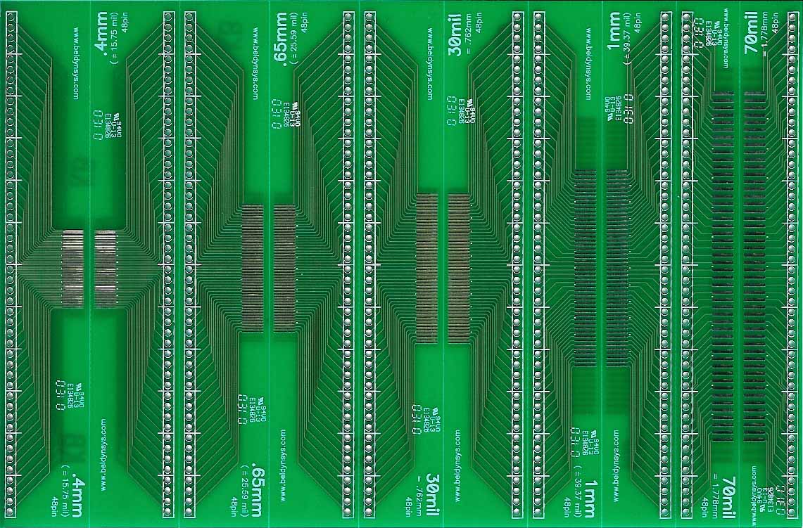
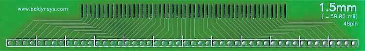
Posted at 2014-06-23 by azrobbo There are adapter boards from Bellin Dynamic Systems and Schmartboard for .4mm pitch. The Bellin B508 module includes two .4mm to .100" breakout modules. http://www.beldynsys.com/p508.htm The adapters for .4mm pitch are on the back. They're designed to snap apart, into modules as pictured below, then you can cut them even smaller if needed: The SchmartBoard Module is the 202-0047-01 http://www.schmartboard.com/index.asp?page=products_connectors&id=319 I'm not sure which would work best for your project. But, it seems like either would be quicker than spinning your own PCB. |

Beta Was this translation helpful? Give feedback.
-
|
Posted at 2014-06-23 by d0773d @azrobbo thanks for taking the time to respond to my question. The connector has 20 pins on the left and 20 pins on the right. Basically I would need something like the Bellin Dynamic Systems SMT adapter boards, but with smt pads that support right and left pins with only one side of breakout out pins. |
Beta Was this translation helpful? Give feedback.
-
|
Posted at 2014-06-23 by azrobbo @d0773d - no worries. Sorry, I didn't realize that you only wanted one row of pins. Unfortunately, I'm not aware of any adapter that brings .4mm pitch items out to a single row of pins. I've seen such adapters for smaller pins counts in more common pitches, but .4mm adapters are fairly rare. You might try posting to the forums at http://www.eevblog.com/forum/ |
Beta Was this translation helpful? Give feedback.
-
|
Posted at 2014-07-02 by d0773d @azrobbo A quick update. I took your advise about posting my question on the eevblog.com/forum; and after chatting back and forth with a user, they helped me create a board using eagle cad. I sent the board info over to iteadstudio to get the board manufactured. It has only been a week since I sent the info to be manufactured so I hope within a week or two I should get a response via email if the boards have been shipped. with UPS shipping it cost cost me 43$ USD for 10 boards and two extra since I checked the opensource option. |
Beta Was this translation helpful? Give feedback.
-
|
Posted at 2014-07-02 by @gfwilliams Nice - it'll be great to see what comes of it. Not bad for 10 boards - you could probably stick the ones you don't use on eBay (or tindie?) - I imagine that other people may want the same thing! |
Beta Was this translation helpful? Give feedback.
-
|
Posted at 2014-07-02 by azrobbo @d0773d Awesome! Thanks for posting the update, and sharing the great news. I'm glad that someone at eevblog was able to help you out. That forum is becoming more and more useful, specifically for electronics & design related discussions. Let us know how the boards look when they come in, and post a pic if you get a chance. Cheers. |
Beta Was this translation helpful? Give feedback.
-
|
Posted at 2014-07-02 by d0773d The boards were shipped out today :) I will post pictures and the eagle files once assembled and if the design works. I now need to figure out how to solder SMT. |
Beta Was this translation helpful? Give feedback.
-
|
Posted at 2014-07-02 by azrobbo Congrats on your inbound boards. This shouldn't be too hard to solder. I'd suggest you read up on 'drag soldering', and test it out a few times before trying it with your 'production' components. There's an article here: http://www.howardelectronics.com/jbc/dragsoldering.html Edited: Removed link to the first video I posted as this one is much better SMT soldering video here: http://www.youtube.com/watch?v=b9FC9fAlfQE |
Beta Was this translation helpful? Give feedback.
-
|
Posted at 2014-07-03 by @gfwilliams As in the video, I've found that flux, copper braid and a clean soldering iron tip make a world of difference. Once those first 2 corners are soldered, doing the rest of the pins is pretty easy. The only issue I had when doing some of the Espruino prototypes was if you're rushing and press too hard against the pins and bend them slightly - but that's easy to avoid. I'd maybe recommend that you find/make something that can press down on the top of the component and steady it. He presses down with some tweezers in the video, but I found my hands are so shaky that the chip occasionally moves around! |
Beta Was this translation helpful? Give feedback.
-
|
Posted at 2014-07-04 by d0773d @gordon @azrobbo Thanks for the tips. O.4mm pitch looks like it will give me a bit of a headache since it looks incredibly small. I'm almost tempted to purchase a relatively cheap video microscope. |
Beta Was this translation helpful? Give feedback.
-
|
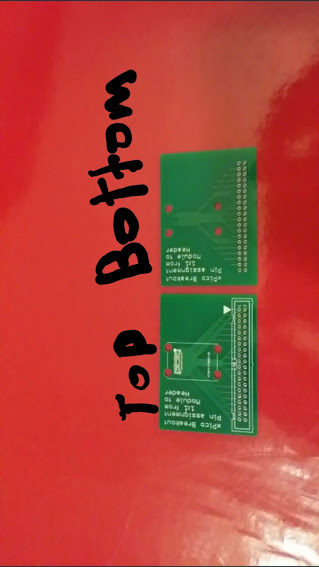
Posted at 2014-07-08 by d0773d My boards arrived today. The boards seem like good quality. However this is my first PCB order so I'm not two sure what "good quality" really is. I don't have a flux pen at the moment and will purchase one tomorrow from the electronics store around the corner from me. Here is a top and bottom picture of one of the boards. I will post another when I am finished assembling. Attachments: |
Beta Was this translation helpful? Give feedback.
-
|
Posted at 2014-07-09 by d0773d @azrobbo @gordon I attempted to solder the small sockets. I tried hot air and the dragging method without any success. I tried pointed tip, small chisel and large chisel. I can get the solder to stick by using a flux pen, however, the drag method creates bridges between a few pins. I tried using the copper wick to soak up the excess solder, but the pins are so small I can't get the solder to wick fully. I think my xPico project is now a bust since I can't get a socket to solder to the breakout. Any other ideas that I could try? |
Beta Was this translation helpful? Give feedback.
-
|
Posted at 2014-07-09 by @gfwilliams Argh. I'm not sure what to suggest... When I can't get rid of the solder bridges I usually just apply a load more flux and try to wick them out again... Worst case I re-add more solder, smooth it around, add then try and wick it out again. It usually works for me. |
Beta Was this translation helpful? Give feedback.
-
|
Posted at 2014-07-09 by d0773d Thanks for the tip Gordon. I think I finally managed to solder the socket onto the breakout board :-) the board seems to have power and I am able to connect to the modules Access point to configure it via wirelessly. Not sure if serial communication works yet, i will check later on today. |
Beta Was this translation helpful? Give feedback.
-
|
Posted at 2016-04-21 by nolando Hi d0773d! It looks like I am in approximately the same position that you were 2 years ago... I'm about to learn PCB design for the explicit purpose of building out a simple breakout board for an xPico. Would you be willing to share the Eagle files for the product you photographed above? |
Beta Was this translation helpful? Give feedback.
-
Posted at 2014-06-22 by d0773d
I'm interested in using lantronix xPico WiFi module(http://www.lantronix.com/device-networking/embedded-device-servers/xpico.html)to the Espruino. The WiFi module uses a 40-pin Board-to-Board SMT Connection to interface with it. Does anyone know of a place where I can buy a 40 pin board-to-board to a 40 pin header so I can use jumper wires to interface with the Espruino? I might be able to manufacture it my self; however, I have never used PCB software before.
Beta Was this translation helpful? Give feedback.
All reactions