RFID module RC522 interfaced to Pico results in various Uncaught Error MFRC522 Request Errors #917
Replies: 20 comments
-
|
Posted at 2017-01-22 by Spocki I think the problem lies in your code: var nfc = require("MFRC522").connect(SPI1, B1/CS/); B1/CS/ is not a pin, use just B1, (/* .... */ is a comment, with missing stars its not!). Presuming that you really connected Pico Pin B1 to the modules CS pin (probably NSS for your board). Your code AND schematics would help a lot ;-) |
Beta Was this translation helpful? Give feedback.
-
|
Posted at 2017-01-22 by Robin Thank you Spocki for the quick response. Good eye on the embedded comment, but that wasn't it. I had block commented out an iteration of the tutorial code, and had to remove the stars to allow the block comment to compile. While creating the forum post in a vanilla editor, I missed the commented out part as it wasn't in color. Proofread, proofread. Regarding the code. I'm just using the tutorial as in [2] above: https://www.espruino.com/MFRC522 Regarding a schematic I thought that page [3] above, explained that well enough but if a pin-to-pin table would help: RC522 Pico Not sure if reset should be held in any particular state. Haven't found documentation, yet. In case it isn't clear, my board (green) mfg is KeyeStudio not the MPN brand (blue) referenced on page [3] available via eBay. Thank you for your response. |
Beta Was this translation helpful? Give feedback.
-
|
Posted at 2017-01-23 by @gfwilliams MISO stands for 'master in slave out' - so it's nice and easy - MISO always connects to MISO, and same for MOSI and SCK. The fact that you're getting an Error 2 makes me think communications are more or less working - if there's a problem you usually get 0 or 255. Could you check that you really have connected the board to 3.3v on the Pico, and not to the 5v output? I came across someone having a very similar issue before, and it was because they were putting too much power on the board. |
Beta Was this translation helpful? Give feedback.
-
|
Posted at 2017-01-23 by Robin Mon 2017.01.23 Gordon, I checked as I wired the board, that I made sure I had a solid ground and that the RC522 was connected to the Vdd 3.3v bus. Just did a sanity check and my VOM indicates the Vdd rail is 3.2v and the 5v rail is 4.8v. I switched USB ports and found all three are 4.8v The Pico seems happy, so we'll live with that for now. Regarding the error codes. As soon as the board powers up and I send the tutorial code via the IDE, without a RFID key card, today I'm getting values of 2, 4, 80, 84 and an occasional 255. [ 0010, 0100, 1000, 1100, 11111111 could these be error flags perhaps? ] Is the error code in hex or is my assumption wrong and this is really decimal? There doesn't seem to be any pattern or sequence, just those values but at every interval as the tutorial code requests. Sometimes "Found card" with no value for the variable 'card' is displayed and the tutorial program immediately exits, leaving the right arrow prompt. This occurs even though there is no RFID card within range. Bizarre. If it is felt that, this maybe a normal communication state then my observation that the KeyeStudio silk screen for MISO and MOSI are swapped on the board I have and the pics at the supplier site for the Arduino wiring diagram are (and opposite) accurate. [4b] Thanks for the clarification on MISO-MISO and MOSI-MOSI. However, this seems counter intuitive as the MISO verbage 'Master In' imples that the from signal should be from a pin of 'Master Out' on the sending device, and therefore MISO-MOSI (incorrect). I'll continue to ponder this as I have accepted your clarification. What would you suggest as the next step? Is there a way to use RST or pull the MISO pins and using console.log() statements, get some onboard RC522 data to provide some clues? I took a peek at the module MFRC522.js [7] and possibly could start a new instance and build out slowly with new method names, and lots of console.log() statements in hopes of attempting to understand the logic, but I'm not sure where to start and what would be valid result data. Has anyone used and had success with the KeyeStudio mfg board? I was able to get that in two days combined with an existing order through Amazon. The MPN mfg board which seems to be readily available in Europe was a three week wait via eBay. Just wondering if this manufacturer has been proven yet. I appreciate your input Gordon, although you probably want to spend more time with the Puck. I'm a late starter here and only learned of the Pico just after the New Year and the Puck wasn't available yet. Will continue to plug away at this RC522 to get at an answer. Robin BTW this Pico is a sweet gem of an idea and I see this taking off over here in the States. For those following along a great wiki on the SPI bus and wiring MOSI and MISO |
Beta Was this translation helpful? Give feedback.
-
|
Posted at 2017-01-24 by Robin cont: Gordon, Would you be so kind as to provide a means that would enable me to override a function in the MFRC522.js module. I've tried a method, and several variants, I have used before inside the DOM, but realize this environment is not Html development. [1] ex: My attempts produce the following error: My hope is that I may garner additional detail that will assist in verifying this board and connectivity. [1] http://stackoverflow.com/questions/4814550/how-to-override-a-function-in-another-javascript-file [2] http://www.ericfeminella.com/blog/2011/11/19/function-overwriting-in-javascript/ |
Beta Was this translation helpful? Give feedback.
-
|
Posted at 2017-01-24 by @MaBecker use this to save the original function: |
Beta Was this translation helpful? Give feedback.
-
|
Posted at 2017-01-24 by @allObjects Took a quick look at the MFRC522 module -www.espruino.com/modules/MFRC522.js. Unfortunately, the 'class' - or the constructor function is not exposed so that you could access the prototype (easily) and follow the instructions you mention by links in your last post how to overwrite... BUT, there is a way, and Espruio - aka @gordon - implemented the code to access the prototype when you have an instance. In the module you find the this code: connect function which says and returns m - an instance of 'MFRC522'. To get to the prototype of the constructor function, you use the instance that The complete code: I intentionally separated module from connect to show that module is an object as well which has only one method (or function) - In the code above - which is an exact copy out of the module - you can apply just any change you want... Now some other good news about JavaScript: you do not need to overwrite the prototype, you just can 'overwrite' by attaching a method (function) to the instance: Depending how the module was minified, none of the above may work because some of the references / values may have gotten a different name or are gone completely. We though can check that by looking at the minified version - www.espruino.com/modules/MFRC522.min.js. The relevant code section is this: You recognize the ...prototype.req=function(... part easily, and unfortunately it confirms - compared with the un-minified source - that the constants of the constant object Again: BUT, do not give up... Because the module mechanism is available locally as well, copy the non-minified code of the module into your Espruino Web IDE sandbox under the name MFRC522Robin.js. When you go to Settings - Project of the Web IDE, you can specify a sandbox 'home' directory by clicking the Select Directory for Sandbox and make a new one - I usually call it something like I guess from here you can take it where you want it to have to be... :} Btw, I got it running pretty nicely myself a while ago as you can take from the conversation save() with modules where .connect() initializes device (such as RFID reader MFRC522). |
Beta Was this translation helpful? Give feedback.
-
|
Posted at 2017-01-24 by @allObjects @robin, originally - for above - I wanted to start of differently... but make it now an appendix: To get the simple things out of way: SPI - Serial Peripheral interface BUS [bus = many on the same (wire)] - follows the Master-Slave topology [master makes this bus to a 1 to many topology]. There is only one master and the master controls all communication that goes on. Therefore, SCK on the master is always output and on all slaves it is always input. Thinking of RS232/USART/1 to 1/peer communication is not much of help here... not to forget is the CS - chip select line - something that makes SPI a typical hardware signal driven bus (vs the data or content driven I2c bus)... of course, purposes are different too, so no surprise. SPI allows very high speeds and contention free communication with simple means compared to (m)any of the other protocols... (it's all relative, though, and depends on the requirements and resources you have). I really like your Gem comment, and there is no doubt about, not even a shadow, that could question this statement - AND THE FACT (just learned a new term: 'creating alternate facts'... When I was reared the world was much a simpler place: this three word term was just three characters in one word: lie). Legalese (and politics) aside, the term DOM - Document Object Model - is a TAG language construct that came from XML and made it into HTML... and was initially just static. Brendan Eich engineously came up with what we today call JavaScript / ECMAScript to breath life in the dead document... and therefore, script pieces are DOM elements as well: it had to be a nail under nails to be hammered on... ;) But that is about all what it shares with DOM... |
Beta Was this translation helpful? Give feedback.
-
|
Posted at 2017-01-24 by @gfwilliams First things first - have you updated the Pico's firmware? that might help. I think the others have done a pretty good job here, but if you want to start hacking around with the module, the easiest way might be to copy the whole thing in verbatim: However loads of people have used this problem without issue - so I'd maybe start from the assumption that it could be a wiring issue or maybe even a faulty reader (but it's unlikely).
The program should always show the arrow prompt (as it effectively runs in the background, allowing you to use the prompt to interact with the interpreter while it's running). If it's not showing the prompt then that could be a sign that something is broken. But as you ask - yes, those error codes are bit fields. If you look at the datasheet on Page 41 it'll show you what they mean: https://www.nxp.com/documents/data_sheet/MFRC522.pdf Importantly Bit 6 (64) which would be part of codes 80 and 84 is:
So if there isn't 5v anywhere on the board, I'd be tempted to say that it might actually be a broken board, with something shorted out on it somewhere? |
Beta Was this translation helpful? Give feedback.
-
|
Posted at 2017-01-25 by Robin Tue 2017.01.24 A quick thank you to those that just responded. A wealth of detailed information has been presented and it is all welcomed. Life's challenges have just gotten in the way of living life and I'll need a bit of time before I can respond to each post response in detail. Those explanations will get me started, and in the mean time . . . . I picked up a high quality RFID card, (would MIFARE be more politically correct as the RC522 chip is a subset of RFID?) and found some surprising detection characteristics. Unlike the security card readers for building access, the scanning technique for KeyeStudio is quite different. Most readers I have encountered needed to be swiped across around an inch or so above the surface, holding the card relatively flat. This KeyeStudio reader required a bit of fiddling to get consistent detection. I discovered the need to approach the antenna at a 45 degree angle, with the card at a 90 degree plane, then remove the card a quarter of an inch above to get the actual trigger as seen by the Pico tutorial software sample. Not sure if this was the intended method and how it was designed, but it seems to be the only way to get a consistent trigger detection event. Anyone able to add their swipe surprises if that different than what I described above? I also tried several different setInterval() settings around the ' nfc.findCards(function(card) ' wrapper and noticed I could get the consistent detection I described previously. The problem is that the detection now triggers a 255 error code as indicated earlier, or the 'Found Card' text response, but without the variable 'card' containing any data. I tried a quick fiddle with that section, with no success. As I dive into the overriding of existing functions, what would be a good place to start in attempting to determine why the 'card' variable never contains any data? Also related, any ideas on how/where to look for the culprit that is causing the 255 error at the lines inside the req() function? The callback getCardSerial() calls req() so I guess both need to be inspected. Still studying the module and trying to understand this black box. Along with the data sheet, this is proving to be a bit intimidating. I'll imagine I'll make further progress by the time this is read overseas tomorrow. More later . . . . |
Beta Was this translation helpful? Give feedback.
-
|
Posted at 2017-01-25 by @gfwilliams In: It's reading the ERROR register, and that is reporting the number 255 - so you'd have to look at the datasheet itself for reasons it's so unhappy. You could try checking inside |
Beta Was this translation helpful? Give feedback.
-
|
Posted at 2017-01-26 by Robin Wed 2017.01.25 Thank you Gordon, that answered my first two questions. Anybody see anything glaringly obvious as to why this doesn't return the expected result? Using the existing module 'read' function and adding a function to the instance object, while maintaining the same existing coding format. Using the spec p.37 37h VersionReg shows the software version and p.66 9.3.4.8 VersionReg register Shows the MFRC522 software version |
Beta Was this translation helpful? Give feedback.
-
|
Posted at 2017-01-26 by @allObjects @robin, I suggest you make a pic of your setup and publish it along with the complete code you try to get working. (Communication with the device is obviously established, therefore trying with other SPI / pin sets may be a mute point.) Something I often do is buying two (or more) examples of this - mostly very - cheap hardware, because spending as much time as you already did - including goodwill - and all the others on a possible dud starts to look ridiculous... it is though justified by the Espruino communities understanding that getting anyone going as easy as possible - no joke or and no cynicism here - is key to Espruino's success and of great gratification on seeing others pulling through. This caring and paying forward speaks volumes about the character of the Espruino community, of whom @gordon is a role model and unprecedented in responsiveness and trustworthiness. |
Beta Was this translation helpful? Give feedback.
-
|
Posted at 2017-01-27 by Robin Thr 2017.01.26 @mabe post #7 As I mentioned I had tried several variants, of which the one you posted was one of them. |
Beta Was this translation helpful? Give feedback.
-
|
Posted at 2017-01-27 by Robin Thr 2017.01.26 @allObjects post #8 Your detailed response was well written and was easy to grasp. One is able to observe you have a complete understanding of the subject matter and you do have a knack for the ability to get into the mind of the reader. Following along was easy, and the reader will appreciate that, spending the additional time to format the content in order to make it an easy read. Bravo, Well Done. You might consider adding the post #8 section as a followup to your link in the same post. but wait, there's more . . . post #9 Appreciate the observation on recognizing the 'Gem' statement from post #5 I firmly believe that which I stated. |
Beta Was this translation helpful? Give feedback.
-
|
Posted at 2017-01-27 by Robin Thr 2017.01.26 @gordon post #10
Yes. VERSION 1v91 BUILD_DATE Jan 12 2017
While searching the forums, only found two other entries centered around RC522 and two others with search term RFID and did not find a single mention of a non MPN manufactured board. I'll stress again that the pinout of KeyeStudio is different. Re-wired the board a second time but still point out that the wiring diagram at the KeyeStudio web site is wired to their image which has the MOSI and MISO pins reversed from the silk screen on the board I have. So, went with the original assumption the board was correct, but was never able to get a card to trigger the recognition event until I reversed those pins. So which is correct? Used the tutorial code verbatim, except for changing B2 to B1 for the Pico. Tutorial MFRC522 Your comments are helping, thank you. More related in post xx below
|
Beta Was this translation helpful? Give feedback.
-
|
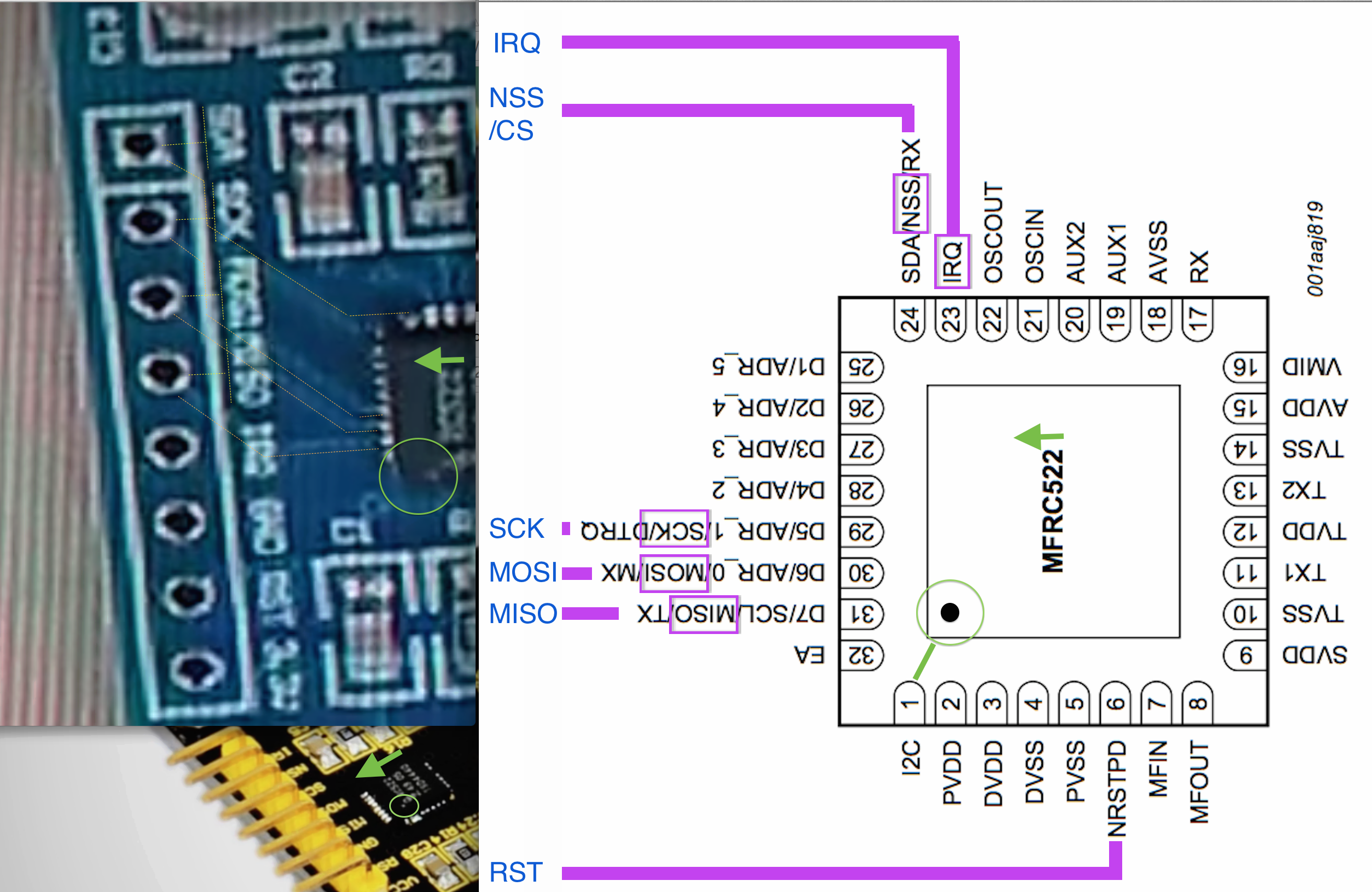
Posted at 2017-01-27 by @allObjects ...btw, cannot see the #XX post... Did look at some boards hanging around and at the RC522 chip... to try to derive the rational for the sequence of the signals on the pin header. Routing (most of) the (significant) signal lines straight forward to the pin header is a good rational for the signal pin sequence
as you can take from attached screen shot. Usually there is not much variation... taking a closer you can actually visually trace the routing / traces from the chip pins to the header pins. Take a closer look at your board and you can confirm. Zoom into the attached picture and you the fine, dotted, orange lines marking the routing for MISO, MOSI, SCK, and CS/SSN/SDA, and the yellow ones indicating the pin and pin function silk screen. (I know that you have a different board... but I' confident that it is not a high-tech (4..6 layer) board hat has front and back top planes covered with all ground for RF reasons and 'hiding' the routing of the signal lines in between these two outermost layers... Something I noticed in many of the usages is connecting the RST to a pin and do a software driven reset before talking to the board... You might do that too. Usually though, an open reset is pulled up by the chip itself. You can take any PICO pin you have left, connect it and use this code: There are better ways to do this for permanent implementation, but it is good enough for figuring out. Something from your post #5 raises concerns:
Why could you read 4.8V on all three? I hope the VCC (3.3v) pin of the MFRC522 break out board was not a member of all three. This could have fried something... for example happened to with a different device specified for 3.3v, when a bread board cable got loose and hit the 5V (4.8V / USB) supplied rail. Interestingly, only a part of the chip was gone - unfortunately it was the essential one. I still could read/write registers, read the configuration info and chip id, but the core function of the chip was enjoying freedom from commands in lala land... :x[. I hope it is just a misreading of your post. Attachments: |
Beta Was this translation helpful? Give feedback.
-
|
Posted at 2017-01-29 by Robin Sun 2017.01.29
To clarify, the PC I powered the Pico with has three USB ports. Using each one at a time, showed a consistent 4.8v sourced. I always wired with the USB plug, unplugged, so there was never any moment when the 3.3v pin would have come in contact with 5v Vcc
Checked the board closely and while power is supplied through shielded 10 gauge solid wire to a screw down terminal block, I have in fact a 16 multi-layer board with 23 through hole feeds, most likely to connect the internal Bluetooth, WiFi, GPS and Puck magnetometer sensor. How did they get all those working parts in a PCB board so small? hmmmmmmmm . . . . I missed fig 3 of section 7 of the spec. Your image detail puts into perspective the relative position of the MOSI and MISO pins. The dark green color of the conformal coat covering the board make it difficult to make out, but not impossible after two ales. I agree with your assessment that the parallel diagonal traces don't cross, so their connection to the header should be in the same relative order. Given that, it can only mean that the silk screen on this board is in fact accurate and the data page at the supplier of the reversed pins is of an earlier board release perhaps. But, that makes my situation more perplexing. Since in order to have acceptable triggering, I had to cross connect MOSI to MISO and had many more triggerings using the tutorial code. When connected MOSI to MOSI, there are never any trigger events. So what is a person to do? The code shouldn't work with the data lines crossed, but it mysteriously does. As I started out in the initial post, don't open packages that arrive on Fri the 13th! I'm at the point where shipping costs to return the KeyeStudio item for an even exchange are prohibitive and with the messing around one has to do re-packaging, purchasing a competitor product entails yet another 3-4 wk wait plus shipping costs. Looks like I got stung on this, and stung big time. |
Beta Was this translation helpful? Give feedback.
-
|
Posted at 2017-01-29 by @allObjects SPI can also run in a 3-wire setting (SIO) vs the usual 4-wires (separate MOSI/MISO). But I do not expect this to play a role her. Can you measure the resistance between / figure out which chip pin (30, 31) is connected board pin? May be the board / or bad soldering made the chip to talk I2C,... which can explain the various value for the same thing... (because the pull-ups are missing). |
Beta Was this translation helpful? Give feedback.
-
|
Posted at 2017-02-04 by Robin Sat 2017.02.04 Finally got a bit of time to continue. Resistance on MOSI, MISO, CLK and NSS are all the same. ~22K pullup and ~5K pulldown when measured between the Vcc and Gnd pins. Every thing seems okay hardware wise. When squinting at the trace solder pads I do see a blob between pins 2 and 3 , but this appears to be intentional. e.g. PVDD to DVDD With as many views of this thread, 340 to date in a little over a week, I'm surprised no one has chimed in with detail on a KeyeStudio board. I may purchase one of the blue MPN boards should I be able to source at Amazon. Since, sourcing via eBay etal, entails some surprising extra fees. Just got my charge card bill for my out of country purchase of Espruino Original, Pico and RC522 and was surprised that yet another fee shows up. Part cost, tax, HST exchange rate fee, S&H and now a currency conversion fee for out of country purchase on a charge card. Yikes! Will it ever end?? The cost to 'get' the part has now exceeded the cost 'of' the part. I wasn't able to find a MPN mfg board locally, but when I do, I'll piggy-back that with another order. Thank you @allObjects for your attention to this post. I'm putting this module on the back burner for a few weeks to move on to something else that is more productive. |
Beta Was this translation helpful? Give feedback.
Uh oh!
There was an error while loading. Please reload this page.
-
Posted at 2017-01-22 by Robin
Sun 2017.01.22
Just jumped into the world of IoT and finding the Pico an undiscovered gem that is about to shine. Toyed with it, running through the gears, while waiting for parts to arrive for fun development.
Here in the USA to reduce an order shipping cost through Amazon Fulfillment I orderd an RFID module to interface with the Pico. [1] The module arrived Friday the 13th. Oooooh, Beware. Superstition aside, read over [2]. Seemed simple enough.
As other tutorials went without a hitch, was surprised when I kept getting:
"Uncaught Error: MFRC522 Request Error 10" which repeated ad infinitum.
<< repeat >>
What I did to troubleshoot. Unfortunately no O-Scope to assist here:
This Espruino forum reference indicated to change B2 to CS/SS/SDA B1 [3]
I also changed the second line of code [2] to reflect that:
var nfc = require("MFRC522").connect(SPI1, B1/CS/);
The supplier video [at 02:46] indicates to make sure IDE is set to 9600, and verified the Espruino IDE was set to 9600, it's default. [4b]
From that same web page, I re-checked the pinout and found the KeyeStudio PCB had silkscreen that differed from their pics at their website. The supplier image silk screen shows pin 4 as MOSI and pin 5 as MISO which are reversed from the silk screen on the boards I have.
The board that arrived - also without a silk screen rev level
Pin
1 Vcc
2 RST
3 Gnd
4 MISO
5 MOSI
6 Clk
7 NSS
8 IRQ
It's not clear in the documentation whether MISO should be wired to MISO -and- MOSI wired to MOSI. Should these be crossed as in RS232 Xmit-Recv ? hmmmm
How I first wired KeyeStudio (as the silk screen correctness is unknown) [5]
pin 4 as MISO to Pico B5 SPI1 MOSI
pin 5 as MOSI to Pico B4 SPI1 MISO
I reversed those pins and then got different error msgs:
140 0x8C
02 0x02
10 0x0A
Was hoping that I could identify a bit(s) that was/wasn't toggling here.
Off to read the spec sheet [6]
It appears that without a scope to assist in watching the clock signals, an option might be to model the MFRC522.js module [7] being careful to use new function names, so as to avoid any name collisions with, that which is already part of the Espruino build. I realize the MFRC522.js module has yet to be built out and I may be one of the few that have made an attempt with RFID. Would like to push on even if I end up with all the arrows in my back. [definition of a pioneer]
Any insight would be greatly appreciated.
Robin
Note to self: Don't accept future shipments on Friday the 13th
[1] Part order RC522
https://www.amazon.com/gp/product/B016KE9D2U/ref=oh_aui_detailpage_o02_s00?ie=UTF8&psc=1
[2] Module MFRC522
https://www.espruino.com/MFRC522
[3] Forum post on RC522 and Pico
http://forum.espruino.com/conversations/269348/#comment12328121
[4] Supplier documentation
http://www.keyestudio.cc/h-pd-118.html
code:
http://www.keyestudio.cc/h-nd-95.html
[5] Pico pinout
https://www.espruino.com/Pico
[6] RC522 Spec Sheet
https://www.nxp.com/documents/data_sheet/MFRC522.pdf
[7] Module MFRC522.js
https://www.espruino.com/modules/MFRC522.js
[eof]
Beta Was this translation helpful? Give feedback.
All reactions