The Game Boy's PPU is the component responsible for feeding the LCD (= the screen) with pixels. This document describes how the PPU renders pixels.
::: tip Terminology
A "dot" is the unit of time within the PPU. One "dot" is one 4 MiHz cycle, i.e. a unit of time equal to 1 ∕ 4194304 of a second. The duration of one "dot" is independent of CGB double speed.
When it is stated that a certain action lengthens mode 3, it implies that mode 0 (HBlank) is shortened to make up for the additional time spent in mode 3, as shown in this diagram.
:::
::: warning Timings caution
Timings here are not tested by a single test ROM (made especially difficult by their resolution being finer than M-cycles).
The information here was largely obtained from an emulator that passes intr_2_mode0* from this test suite, but not all of it has been verified from e.g. hardware schematics.
:::
{{#include imgs/src/ppu_overview.svg:2:}}
The Game Boy's rendering process, at its core, works using two queues of pixels, also known as the pixel FIFOs: one for "background" pixels, one for OBJ pixels1. (The Window largely piggybacks on the BG rendering mechanism, more on that below.)
Every "dot", one pixel is shifted off of both FIFOs, and one of them is selected for output. Its corresponding palette is then applied, and the resulting signal sent to the LCD.
When a FIFO needs to be refilled, it calls on the Pixel Slice Fetcher to fetch a slice of 8 pixels, that is, one row from a tile. The BG FIFO is refilled every time it becomes empty; the OBJ FIFO instead requests a refill when an OBJ should start being drawn on the current scanline.
Since the Pixel Slice Fetcher is shared by both FIFOs, when both of them need to be refilled at the same time, pixels temporarily stop being output until both have been served.
The Pixel Slice Fetcher is told which of the 384 tiles to fetch one slice from, as well as which slice of that tile's 8, by the "fetchers"—again, one for the background and window, another for OBJs. These "fetchers" also directly transmit some metadata to the FIFOs2, such as the palette, priority, etc.
Actually, there are more than 2 FIFOs. For example, on DMG, there are two FIFOs for BG pixel indices, two for OBJ pixels, one for OBJ palette bits, and one for OBJ-to-BG priority bits. However, since many are clocked and refilled together, such as the first two or the latter four, it's easier to treat them as a single FIFO that groups all that info under one "pixel".
Again, since the two conceptual FIFOs are really a collection of a bunch of hardware FIFOs, what actually happens is that the "fetchers" directly refill some of these FIFOs, and instruct the Pixel Slice Fetcher to refill the corresponding pixel data FIFO.
Each FIFO can hold up to 8 pixels, the width of one tile. The BG FIFO and Pixel Slice Fetcher work together to ensure that the former never runs out of pixels; the OBJ FIFO is only refilled when an OBJ is "hit".
Each pixel in a FIFO is composed of four properties:
- Color index: a value between 0 and 3.
- Palette:
- On DMG, this contains the palette bit from OAM attributes. Of course, only the OBJ FIFO has this.
- On CGB, a value between 0 and 7 (for BG, the palette bits from BG attributes; for OBJ, the palette bits from OAM attributes).
- Source OBJ: only applies to the OBJ FIFO on CGB. This contains the ID of the OBJ the pixel originated from.
- Priority:
- OBJ FIFO: holds the OBJ-to-BG Priority bit from the OBJ's attributes.
- BG FIFO, on CGB only: holds the OBJ-to-BG priority bit from the tile's attributes.
Every scanline, the following occurs in order:
-
Mode 2:
- OAM is scanned for Y positions in range (based on
LYandLCDC); the X coordinate is not checked! - The first 10 matches get their X and Y coordinates stored in an "OBJ slot". The fact that there are 10 such slots is why only 10 objects can be displayed per scanline3.
This operation takes 2 dots per OBJ, which, multiplied by 40 OBJs in OAM, gives Mode 2's length of 80 dots.
- OAM is scanned for Y positions in range (based on
-
Mode 3:
During Mode 3, on each dot, the FIFOs are clocked, and one pixel output to the LCD. The Pixel Slice Fetcher continuously runs in parallel to refill the BG FIFO. If the OBJ FIFO needs to be refilled, both FIFOs temporarily stop being clocked while the OBJ FIFO "steals" the Pixel Slice Fetcher to get its pixels.
Additionally, in the middle of the scanline, the window may be triggered; this is described in further detail below.
-
Mode 0:
Once the last pixel has been output, the PPU releases the VRAM bus, and does nothing while it waits for the scanline to end.
The PPU embarks both a vertical counter (exposed as LY), and a horizontal counter, which will be referred to as "LX" henceforth.
Since these 10 object slots are only refilled during Mode 2, and there appears to be no way to manipulate the PPU mode in the middle of a scanline, it seems that this limitation cannot be worked around.
The fetcher grabs a row of 8 pixels at a time to be fed to either FIFO. Data is fetched from VRAM one byte at a time, thus pixels are always fetched 8 at a time4 (hence the FIFOs' width).
The following steps are executed, in this order:
Well, since pixels are 2bpp, two fetches are necessary—but one still ends up with 8 pixels, since the VRAM data bus is 8-bit.
This step determines which background/window tile to fetch pixels from. This step is not executed by the Pixel Slice Fetcher itself, but rather by the active "fetcher":
During this step, a tilemap is sampled to determine which tile to fetch.
The address read depends on whether the BG fetcher is in "BG mode" or "Window mode":
| Mode | 15 | 14 | 13 | 12 | 11 | 10 | 9 | 8 | 7 | 6 | 5 | 4 | 3 | 2 | 1 | 0 |
|---|---|---|---|---|---|---|---|---|---|---|---|---|---|---|---|---|
| BG | 1 | 0 | 0 | 1 | 1 | LCDC bit 3 | (LY + SCY) ∕ 8 | (LX + SCX) ∕ 8 | ||||||||
| Window | LCDC bit 6 | "Window Y" ∕ 8 | LX ∕ 8 | |||||||||||||
::: tip Wrapping
The two additions in the "BG mode" row are carried out in 8 bits, i.e. modulo 256. Due the division by 8, the modulo is essentially 32, i.e. a tilemap's width. This is what causes the background to wrap around, both vertically and horizontally.
:::
A byte is read from the computed address, and is forwarded to the Pixel Slice Fetcher as a tile ID. Color models read from the computed address twice: from VRAM bank 0 to get the tile ID, and from VRAM bank 1 to get the attributes.5
::: tip Raster effects
Interestingly, unlike e.g. the NES' PPU, great care has been taken to ensure that the BG fetcher re-reads as many registers as possible (SCY, LCDC, etc.).
This may have been insight from the former console, on which proper "raster splits" are quite tricky due to a lot of internal caching.
:::
This step takes 2 dots, with the VRAM access(es) being performed on the second.
Both appear to be accessed during the same dot, which implies that the PPU can access both VRAM banks at the same time.
Since the Pixel Slice Fetcher is normally used continuously for the BG FIFO, the OBJ fetcher waits to take control until two conditions are met:
- The Pixel Slice Fetcher is attempting to push pixels
- The BG FIFO is not empty
Once both conditions are fulfilled, the OBJ FIFO takes over, discarding the pixels slices already fetched. Note that if the BG FIFO is empty, the Pixel Slice Fetcher immediately switches to Get tile ID when refilling it, so the OBJ fetcher will wait for 6 additional dots.
OAM is then read for the tile ID and attributes (TODO: timings are unknown); if the PPU cannot access OAM (for example due to OAM DMA), $FF is read.
If the OBJ size is 8×16, the bottom bit of the tile ID is overridden depending on whether the upper or lower half of the OBJ was hit.
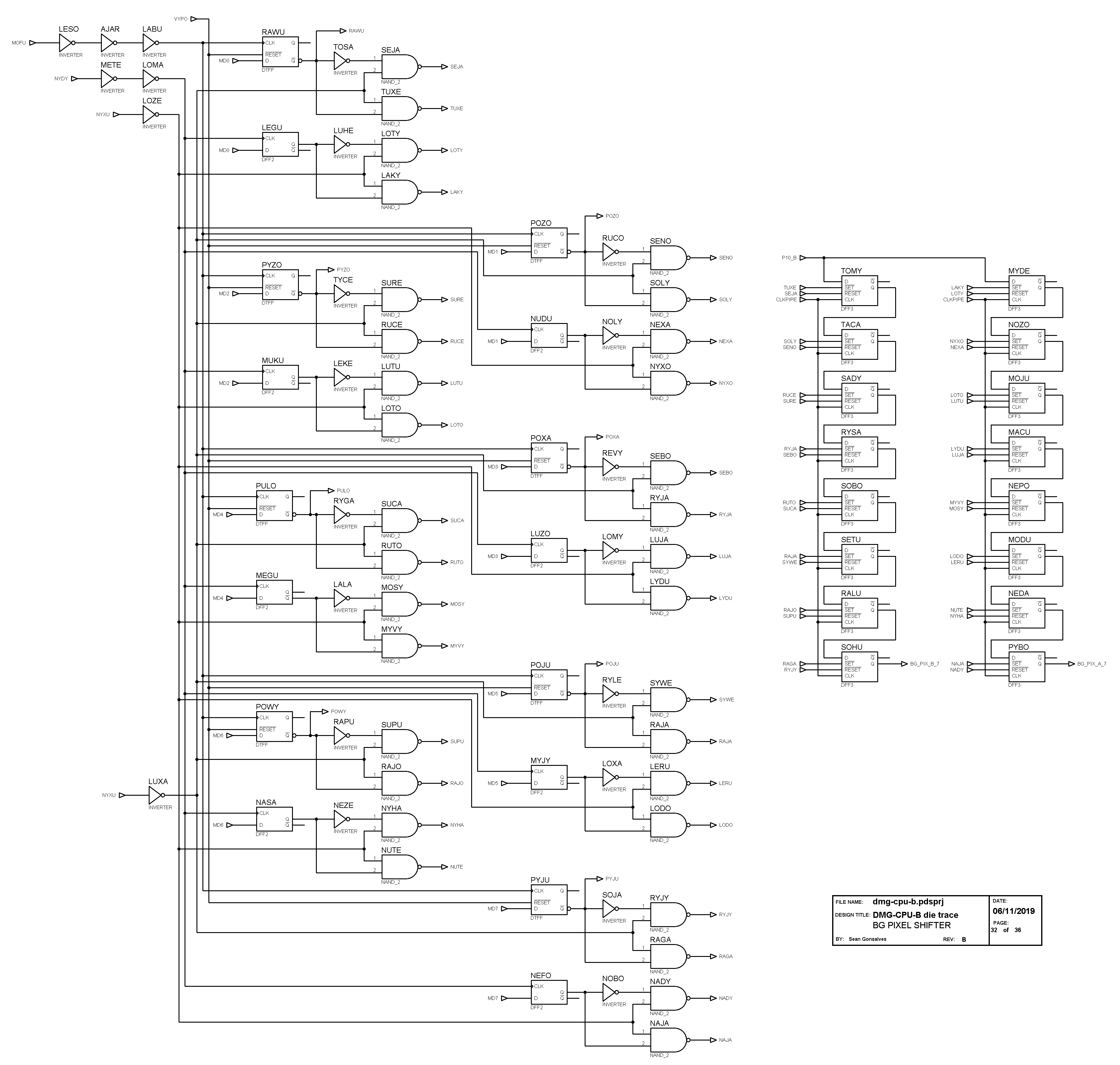
(See gate GEJY in the schematics.)
Additionally, if the OBJ is flipped vertically, this override will be inverted (gates WUKY and WAGO).
::: warning LCDC bit 1
LCDC bit 1 toggles whether OBJs are displayed, but the implementation is very different on DMG and CGB.
On all models, LCDC bit 1 controls whether pixels from the OBJ FIFO are selected; however, on monochrome models, LCDC bit 1 being off also causes the OBJ fetcher to be disabled entirely.
This differs in two important ways:
- On DMG, clearing
LCDCbit 1 causes OBJs not to incur any Mode 3 length penalties; on CGB, Mode 3 length is not affected byLCDCbit 1. - Setting the bit back to 1 in the middle of an OBJ being (putatively) displayed will cause it to appear on CGB, but not on DMG, since its pixels aren't in the OBJ FIFO.
And importantly as well, this behavior remains in the Color's compatibility mode, making software behave potentially differently.
:::
During this step, the first of the slice's two bitplanes is fetched. The address being read from is computed like this:
| Mode | 15 | 14 | 13 | 12 | 11 | 10 | 9 | 8 | 7 | 6 | 5 | 4 | 3 | 2 | 1 | 0 |
|---|---|---|---|---|---|---|---|---|---|---|---|---|---|---|---|---|
| BG | 1 | 0 | 0 | See below | Tile ID | (LY + SCY) mod 8 | 0 | |||||||||
| Window | "Window Y" mod 8 | |||||||||||||||
| OBJ | 0 | LY - OBJ Y mod 8 | ||||||||||||||
For BG/Window tiles, bit 12 depends on LCDC bit 4.
If that bit is set ("$8000 mode"), then bit 12 is always 0; otherwise ("$8800 mode"), it is the negation of the tile ID's bit 7.
The full logical formula is thus: !((LCDC & $10) || (tileID & $80)) (see gate VUZA in the schematics).
On CGB, which VRAM bank the byte is fetched from, is determined from the attributes' bit 3 (BG, OBJ).
If the tile is flipped vertically (attributes bit 6), bits 1–3 of the address are inverted. If the tile is flipped horizontally (attributes bit 5), the byte read is flipped around. (The timing of horizontal flipping has not been verified.)
This step takes 2 dots.
Exactly the same as Get tile slice (low), except the following byte is fetched (i.e. bit 0 of the address is 1 instead of 0). This step takes 2 dots as well.
Interesting phenomena can be triggered by changing the address' "parameters" between the two bitplane reads, called "bitplane desyncing".
Since VRAM and OAM cannot be modified during Mode 3 (though OAM DMA can change what the PPU reads from OAM), the parameters that can be changed are SCY and LCDC bit 4.
Modifying SCY causes the second bitplane (and also the first one, depending on timing) to be read from a different Y offset within the tile than normal.
This does not occur starting with CGB revision D, including AGBs: SCY is internally latched during the tilemap read, so both bitplanes are always read correctly.
(Compare CGB-C and CGB-D.)
Modifying LCDC bit 4 exhibits much more complex behavior, explained in this document by mattcurrie.
Once the fetcher reaches this state, it will attempt to push the two bytes it read, plus associated metadata, into the target FIFO on every dot.
The BG FIFO will only accept pixels when it's empty.
The OBJ FIFO needs to "merge" the pixels being pushed with the pixels it already contains. This decision leads to what is conceptually known as "OBJ-to-OBJ priority". Note that overwriting a pixel entails not only replacing its ID, but also any attached attributes, such as the palette, etc.
- On DMG and on CGB in Non-CGB Mode, the algorithm is simply that only pixels with an ID of 0 (= transparent pixels) are overwritten. Since OBJ pixels are inserted as the OBJs are encountered horizontally, pixels inserted earlier, thus from objects with lower X positions, will have priority.
- On CGB in CGB Mode, OBJ pixels also store the ID of the OBJ they originated from, and get overwritten by pixels from OBJs with lower IDs.
Every time both FIFOs are clocked, the selector decides whether to retain the pixel from the BG or OBJ FIFO.
The selection follows the following rules:
- In CGB Mode, if
LCDCbit 0 (priority enable) is reset, pick the BG pixel. - In Non-CGB Mode, if
LCDCbit 0 (BG & Window enable) is reset, pick the OBJ pixel. - If
LCDCbit 1 (OBJ enable) is reset, pick the BG pixel.⚠️ See above for a note about this bit. - In CGB Mode, if the BG pixel has its priority bit set, and its ID is not 0, pick the BG pixel.
- If the OBJ pixel has its priority bit set, and the BG pixel's ID is not 0, pick the BG pixel.
- If the OBJ pixel is 0, pick the BG pixel; otherwise, pick the OBJ pixel.
Once a pixel has been selected, the corresponding palette is applied:
- Non-CGB Mode: BG pixels use
BGP; OBJ pixels useOBP0if attributes bit 4 is reset, andOBP1otherwise. - CGB Mode: Palette n is used, where n is bits 0–2 of the pixel's corresponding attributes (BG, OBJ). BG palettes are used for BG pixels, OBJ palettes are used for OBJ pixels.
The pixel's 2-bit ID is used to index the 4-color palette, and the resulting color is sent to the LCD.
Besides the pixels, a few signals are sent to the LCD.
...
As stated before the pixel FIFO only operates during mode 3 (pixel transfer). At the beginning of mode 3 both the background and OAM FIFOs are cleared.
When rendering the window the background FIFO is cleared and the fetcher is reset to step 1. When WX is 0 and the SCX & 7 > 0 mode 3 is shortened by 1 dot.
When the window has already started rendering there is a bug that occurs when WX is changed mid-scanline. When the value of WX changes after the window has started rendering and the new value of WX is reached again, a pixel with color value of 0 and the lowest priority is pushed onto the background FIFO.
The following is performed for each object on the current scanline if LCDC.1 is enabled (this condition is ignored on CGB) and the X coordinate of the current scanline has a object on it. If those conditions are not met then object fetching is aborted.
At this point the fetcher is advanced one step until it's at step 5 or until the background FIFO is not empty. Advancing the fetcher one step here lengthens mode 3 by 1 dot. This process may be aborted after the fetcher has advanced a step.
When SCX & 7 > 0 and there is a object at X coordinate 0 of the current scanline then mode 3 is lengthened. The amount of dots this lengthens mode 3 by is whatever the lower 3 bits of SCX are. After this penalty is applied object fetching may be aborted. Note that the timing of the penalty is not confirmed. It may happen before or after waiting for the fetcher. More research needs to be done.
After checking for objects at X coordinate 0 the fetcher is advanced two steps. The first advancement lengthens mode 3 by 1 dot and the second advancement lengthens mode 3 by 3 dots. After each fetcher advancement there is a chance for a object fetch abortion to occur.
The lower address for the row of pixels of the target object tile is now retrieved and lengthens mode 3 by 1 dot. Once the address is retrieved this is the last chance for object fetch abortion to occur. Exiting object fetch lengthens mode 3 by 1 dot. The upper address for the target object tile is now retrieved and does not shorten mode 3.
At this point VRAM Access is checked for the lower and upper addresses for the target object. Before any mixing is done, if the OAM FIFO doesn't have at least 8 pixels in it then transparent pixels with the lowest priority are pushed onto the OAM FIFO. Once this is done each pixel of the target object row is checked. On CGB, horizontal flip is checked here. If the target object pixel is not white and the pixel in the OAM FIFO is white, or if the pixel in the OAM FIFO has higher priority than the target object's pixel, then the pixel in the OAM FIFO is replaced with the target object's properties.
Now it's time to render a pixel! The same process described in Sprite Fetch Abortion is performed: a pixel is rendered and the fetcher is advanced one step. This advancement lengthens mode 3 by 1 dot if the X coordinate of the current scanline is not 160. If the X coordinate is 160 the PPU stops processing objects (because they won't be visible).
Everything in this section is repeated for every object on the current scanline unless it was decided that fetching should be aborted or the X coordinate is 160.
This is where the background FIFO and OAM FIFO are mixed. There are conditions where either a background pixel or a object pixel will have display priority.
If there are pixels in the background and OAM FIFOs then a pixel is popped off each. If the OAM pixel is not transparent and LCDC.1 is enabled then the OAM pixel's background priority property is used if it's the same or higher priority as the background pixel's background priority.
Pixels won't be pushed to the LCD if there is nothing in the background FIFO or the current pixel is pixel 160 or greater.
If LCDC.0 is disabled then the background is disabled on DMG and the background pixel won't have priority on CGB. When the background pixel is disabled the pixel color value will be 0, otherwise the color value will be whatever color pixel was popped off the background FIFO. When the pixel popped off the background FIFO has a color value other than 0 and it has priority then the object pixel will be discarded.
At this point, on DMG, the color of the pixel is retrieved from the BGP register and pushed to the LCD. On CGB when palette access is blocked a black pixel is pushed to the LCD.
When a object pixel has priority the color value is retrieved from the popped pixel from the OAM FIFO. On DMG the color for the pixel is retrieved from either the OBP1 or OBP0 register depending on the pixel's palette property. If the palette property is 1 then OBP1 is used, otherwise OBP0 is used. The pixel is then pushed to the LCD. On CGB when palette access is blocked a black pixel is pushed to the LCD.
The pixel is then finally pushed to the LCD.
At various times during PPU operation read access to the CGB palette is blocked and a black pixel pushed to the LCD when rendering pixels:
- LCD turning off
- First HBlank of the frame
- When searching OAM and index 37 is reached
- After switching from mode 2 (oam search) to mode 3 (pixel transfer)
- When entering HBlank (mode 0) and not in double speed mode, blocked 2 dots later no matter what
At various times during PPU operation read access to the CGB palette is restored and pixels are pushed to the LCD normally when rendering pixels:
- At the end of mode 2 (oam search)
- For only 2 dots when entering HBlank (mode 0) and in double speed mode
::: tip Note
These conditions are checked only when entering STOP mode and the PPU's access to CGB palettes is always restored upon leaving STOP mode.
:::
Sprite fetching may be aborted if LCDC.1 is disabled while the PPU is fetching an object from OAM. This abortion lengthens mode 3 by the amount of dots the previous instruction took plus the residual dots left for the PPU to process. When OAM fetching is aborted a pixel is rendered, the fetcher is advanced one step. This advancement lengthens mode 3 by 1 dot if the current pixel is not 160. If the current pixel is 160 the PPU stops processing objects because they won't be visible.