Course Project: Control System Lab (CSL) Institution: National Taipei University of Technology (NTUT), Dept. of Electrical Engineering Semester: 114-1 (2025 Autumn) Author: Annie Huang (第一組 111310452)
Technical Report (ZH) (Link) Technical Report (EN) (Link)


This project implements a closed-loop control autonomous vehicle capable of object tracking and distance maintenance using ultrasonic feedback.
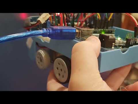
Unlike typical Arduino projects that rely on pre-made motor driver modules (e.g., L298N), this project features a custom-designed H-Bridge driver built from discrete components (BJTs and Relays). This approach demonstrates a deep understanding of low-level hardware control, current paths, and back-EMF protection.
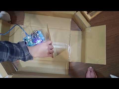
This project is a retrofitting initiative. I repurposed an old primary school educational toy car chassis, bypassing its original limitations by building a custom driver circuit and implementing modern control algorithms (Bang-Bang with Deadband) on an Arduino.

Instead of using integrated driver ICs, the motor driver is hand-crafted to isolate control logic from power actuation:
- Direction Control: Implemented using S8550 (PNP) transistors driving DPDT Relays.
- Speed Control: Implemented using 2SC1384 (NPN) power transistors for PWM low-side switching.
- Protection: Integrated 1N4001 Flyback Diodes to absorb inductive kickback from relays.
To handle the noisy data typical of low-cost ultrasonic sensors:
- Median Filter: Implemented a bubble-sort algorithm to sample 5 readings and pick the median, effectively eliminating outliers (spikes).
- Deadband Control: defined a tolerance range () to prevent motor oscillation (chattering) when the target distance is reached.
- Dual-Layer Logic:
- Spot Turn: For large errors, the car rotates in place.
- Differential Drive: For small errors, the car adjusts wheel speeds individually for smooth correction.
| Component | Specification | Quantity | Function |
|---|---|---|---|
| Controller | Arduino Uno | 1 | Central Processing Unit |
| Sensor | HC-SR04 | 2 | Ultrasonic Distance Measurement |
| Transistor | S8550 (PNP) | 2 | High-side Switch (Relay Driver) |
| Transistor | 2SC1384 (NPN) | 2 | Low-side Switch (PWM Speed Control) |
| Relay | DPDT (5V) | 2 | Motor Direction Reversal |
| Diode | 1N4001 | 2 | Flyback/Back-EMF Protection |
| Motor | DC Gear Motor | 2 | Drive Train |
| LED | Red/Green/Blue | 4 | State Indication (Forward/Back/Left/Right) |
The system isolates the MCU control signals from the motor power supply.
- Pin 2/7 (Digital): Controls S8550 -> Relay (Direction).
- Pin 3/6 (PWM): Controls C1384 (Speed).
- Pin 4/5 & 10/11: HC-SR04 Trigger/Echo.
The core control loop runs in ultrasonic_control_motor.ino:
- Sensing: Read raw data from Left/Right HC-SR04 sensors.
- Filtering: Apply Median Filter to remove noise.
- Error Calculation:
Diff = Left_Dist - Right_Dist(Orientation Error)Dist_Err = Target - Current_Dist(Position Error)
- Decision Making:
- Case 1: Large Orientation Error: Trigger Spot Turn.
- Case 2: Distance Error > Tolerance: Move Forward/Backward with Differential Steering.
- Case 3: Within Deadband: Stop motors (AnalogWrite 0).
.
├── ultrasonic_control_motor.ino  # Main Arduino Source Code
├── test_relay.ino                # Testing Relay Function
├── test_ultra_sound.ino          # Testing Ultrasonic Sensor Function
├── circuit_diagram.png           # Hardware Schematic
└── README.md                     # Project Documentation
- Clone this repository.
- Open
ultrasonic_control_motor.inoin Arduino IDE. - Verify the pin definitions match your wiring (defined in the top of the file).
- Upload to Arduino Uno.
- Open Serial Monitor (9600 baud) to view real-time distance data and filter performance.
This project is open-source for educational purposes.
Created by Annie Huang, NTUT EE. 2026